A Complete Guide to Building a Hand-Wired Keyboard
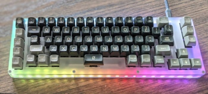
Table of Contents
Recently I was looking for a new keyboard for my home workstation. I have a strong fondness for mechanical keyboards, and while there are amazing options available on the market none were exactly what I was looking for. Then it dawned on me, why not build something custom? I had access to the tools, I love to build and create, and (oddly) love to solder. So began the journey to build a custom mechanical keyboard.
Hardware Needed
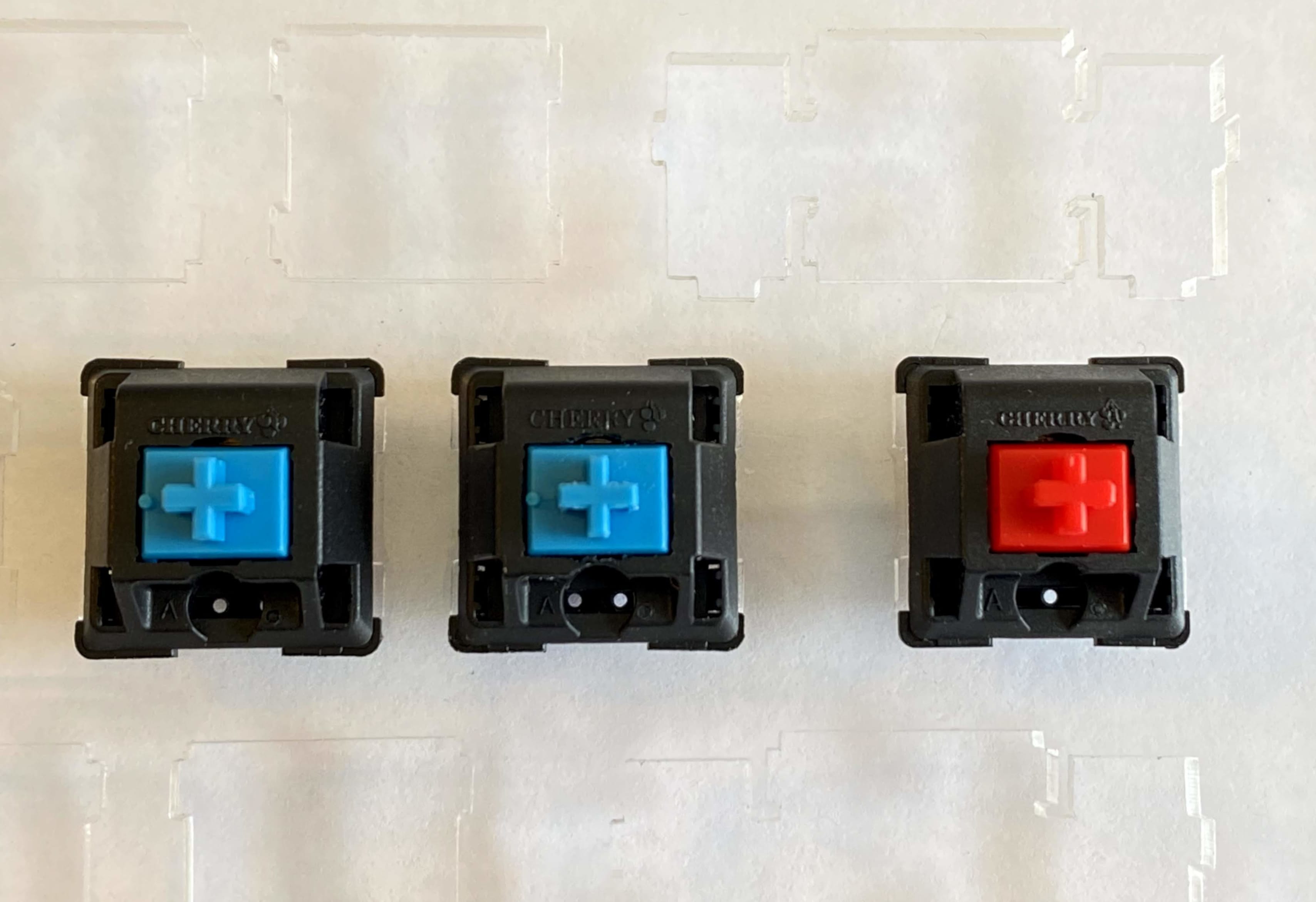
- There are an amazing number of keyboard switches available. Do your research, and narrow down the switch feel you’re after. If you have a community of keyboard enthusiasts nearby, you can likely try out someone’s keyboard before making a switch purchase. If you’re unsure, Cherry MX are the most common, and are organized by color. Cherry MX Blues are “clicky”, and provide a tactile feel. Cherry MX Browns provide a tactile feel but don’t have the same audible “click”, Greens are stiffer, Reds require a very light tough to engage. For this project, I’m using a combination of MX Blue and MX Red.
- You will need as many key switches as you have keys on the keyboard. For this keyboard I needed 72 switches. Order a few more than you need - just in case.
A diode is an electronic component which only allows for the flow of current in one direction. To allow for the use of a microcontroller which does not have one input for each key on the keyboard we will be wiring this keyboard into a matrix. This allows us to connect more than one switch into an input of a microcontroller.
The microcontroller applies current to each column of the matrix, column by column and checks to see which row outputs current, thereby indicating which key has been pressed. Later on, you will create the software layout of your keyboard, defining which key is at which column/row.
There are some fantastic resources which explain this concept in great depth.
You will need as many diodes as you have keys on the keyboard. For this keyboard, I needed 72 - but ordered 80.
A custom built plate and case for your keyboard.
- The keyboard plate is the rigid base that your key switches are mounted into.
- The keyboard case, is the surrounding which encases the key switches and associated electronics and wiring.
- Key caps are the “keys” of your keyboard. There are so many different styles, the possibilities are almost endless.
- You do need to pay attention to the stem for your key caps. As the key cap connects to the key switch, that interface needs to be compatible. Luckily there are only a few standards readily available, and the most common by far is Cherry MX. When you purchase your key caps, ensure they’re compatible with the key switches you’ve selected.
QMK Compatible Microcontroller
- The microcontroller is the device which is wired into your key switch matrix, allows you to define your keyboard layout and enables your keyboard to interface with your PC successfully.
- I’m using a Teensy 2.0 for this build.
LED Lighting (Optional)
- If you wish to have LED underglow lighting, you’ll need to pick up some WS2812B-compatible LEDs.
Wiring
- You’ll need some solid core and stranded cable to wire up your keyboard. For this build I used some spare 18/5 Thermostat wire for the rows and columns, and the individual wires from an old CAT-5 network cable to wire up the microcontroller.
Software Needed
Keyboard Layout Editor (KLE)
- KLE provides a graphical interface for designing and customizing your keyboard. It interfaces nicely with Github for versioning, and outputs JSON which can be used as the design for your case.
- The swillkb Plate & Case builder will take the JSON output from KLE, and generate the needed CAD files for use in fabricating your design. Because we’re hand wiring this keyboard, at a minimum you will need a plate for the key switches to mount into.
Quantum Mechanical Keyboard Firmware (QMK)
The goal of the QMK software project is to develop a completely customizable, powerful, and enjoyable firmware experience for any project - keyboard or otherwise - and to provide helpful, encouraging, and kind support and feedback for people with any software development experience.
- We’re using QMK to interface with and drive our keyboard
Getting Started
This is a straightforward project, but takes time and patience. I would suggest doing a lot of reading and research to better understand what you’re building . This is not a complicated project, but I’ve always found it helpful to have a baseline level of knowledge for those times where you get stuck, or something isn’t working exactly as you thought it would.
Designing Your Keyboard
Producing a Design
To start, you need a design. Work with KLE to build and customize the keyboard as you’d like. At this point you want to focus on the overall design of your keyboard. Make sure the layout is as you’d like and you have the keys you want. When I was close to finished with my design, I found it helpful to download and print a PNG image of the keyboard to make sure the digital design translated well to the physical world. This was useful to understand the overall dimensions of the keyboard as designed.
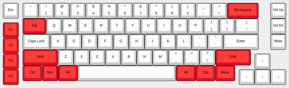
In my design I’m using Cherry MX Blue switches for the majority of the keys, and Cherry MX Reds for some of the function-type keys. In KLE I’ve colored those keys red as a reference for when I’m building.
When you have a design that you’re happy with, click on the “Summary” tab within KLE, which produces a Bill of Materials, detailing the types and quantities of supplies you’ll need for this keyboard. You can reference these quantities when ordering the key switches, diodes and keycaps.
Producing the Plate and Case
Again from within KLE, click on the “Raw data” tab. This will produce the JSON representation of your keyboard, which can be used as the input to the swillkb Plate & Case Builder :
[{a:7},"Esc",{x:0.25,a:5},"~\n`","!\n1","@\n2","#\n3","$\n4","%\n5","^\n6","&\n7","*\n8","(\n9",")\n0","_\n-","+\n=",{c:"#dd1126",st:"MX1A-L1xx",a:7,w:2},"Backspace",{x:0.75,c:"#cccccc"},"Vol Up"],
[{x:1.25,c:"#dd1126",w:1.5},"Tab",{c:"#cccccc"},"Q","W","E","R","T","Y","U","I","O","P",{a:5},"{\n[","}\n]",{w:1.5},"|\n\\",{x:0.75,a:7},"Vol Dn"],
[{y:-0.75,c:"#dd1126"},"F1"],
[{y:-0.25,x:1.25,c:"#cccccc",w:1.75},"Caps Lock","A","S","D",{n:true},"F","G","H",{n:true},"J","K","L",{a:5},":\n;","\"\n'",{a:7,w:2.25},"Enter",{x:0.75},"Mute"],
[{y:-0.75,c:"#dd1126"},"F2"],
...snip...
Copy the raw JSON data from KLE and paste that data into the “Plate Layout” section of swillkb. Work your way through the various options and when you’re finished click “Draw My CAD!!!”
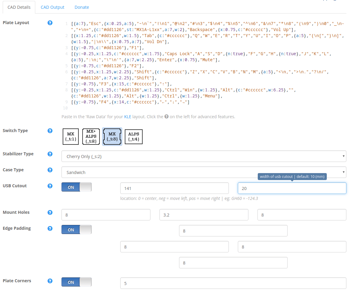
swillkb will process your KLE data along with the configuration options you selected to produce a visual representation of the plate and case components needed for your keyboard.
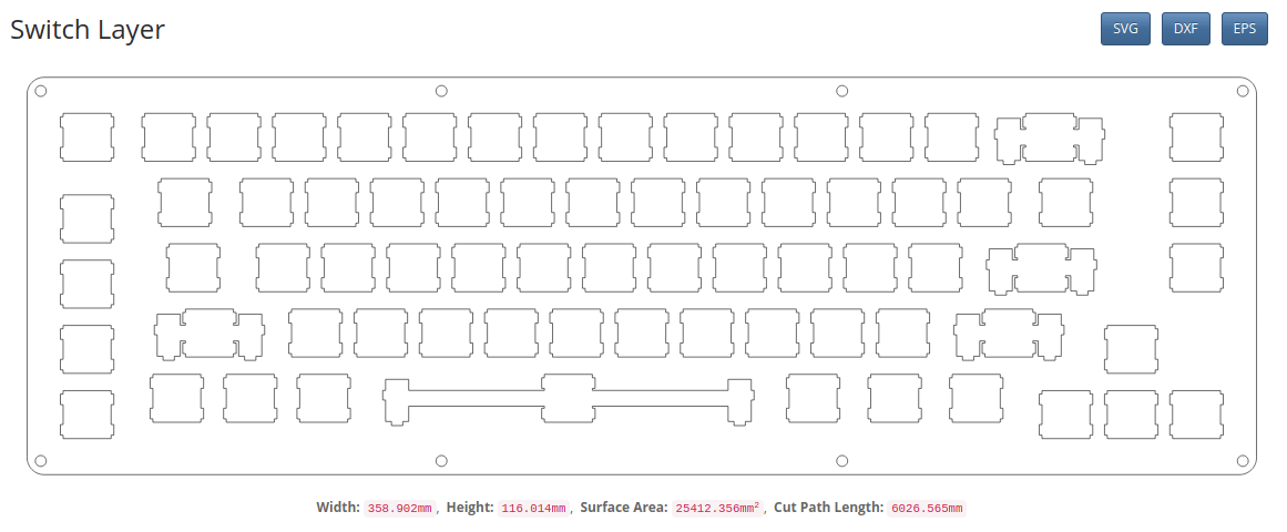
Again here, I would recommend printing this image of your keyboard, to ensure it’s the size you were expecting.
Once you have the design and configuration to your liking, you’ll need to produce both the plate and case. There are a number of online services which will fabricate your parts from a variety of materials, swillkb has a nice integration with lasergist which is a cost-effective option.
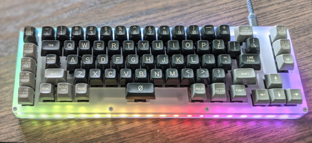
I’m fortunate to have access to a laser cutter, so I fabricated my plate and case myself from acrylic.
Key Switch Installation
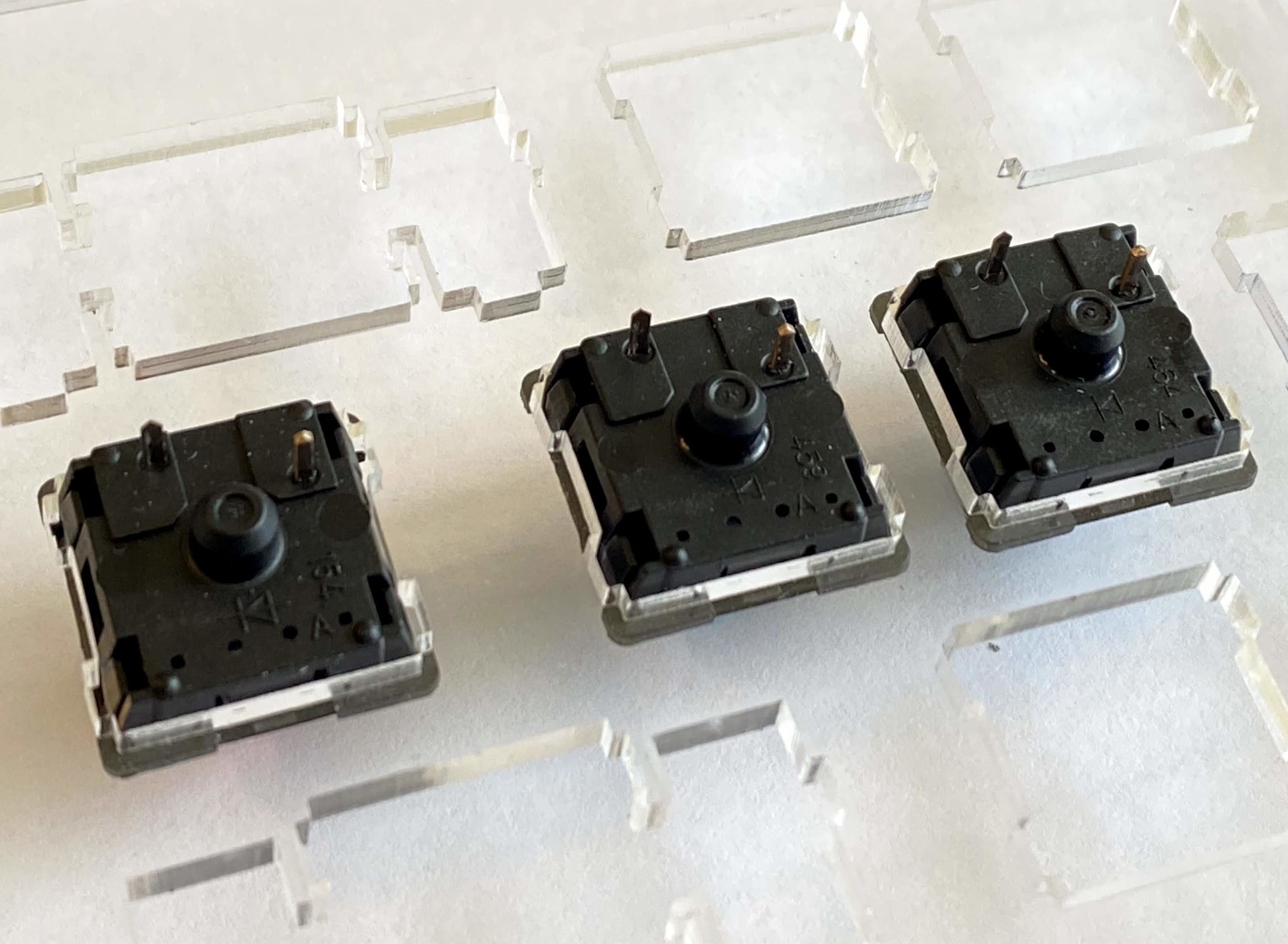
Once you have your keyboard plate and key switches in hand, you’re ready to begin the build for your keyboard. Key switch installation is very straightforward, and is the easiest part of this build - simply snap the key switch into the plate. Ensure that the pins on the back of the switch are facing the top edge of your keyboard. With Cherry switches you can use the logo on the switch as a visual reference. Ensure the logo is at the top of the switch, and towards the top of your keyboard.
Once you have all key switches installed, it’s time to move onto the diode installation.
Hand-Wiring Your Keyboard
This is the most laborious parts of the build. Again, nothing terribly complicated, but it’s fiddly work and will take some time. You’ll be wiring and soldering each key switch at least twice, but there are some tricks which will make this much easier.
Key Switch Diode Installation
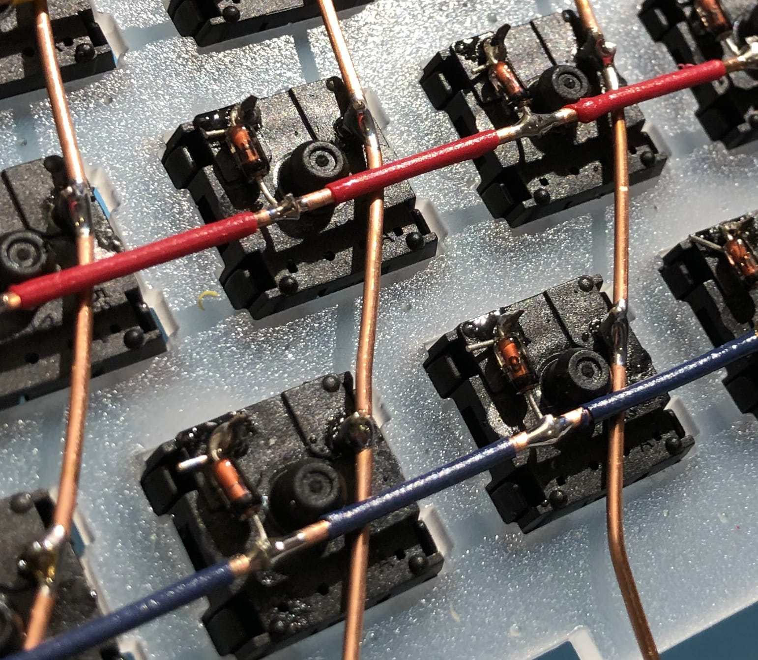
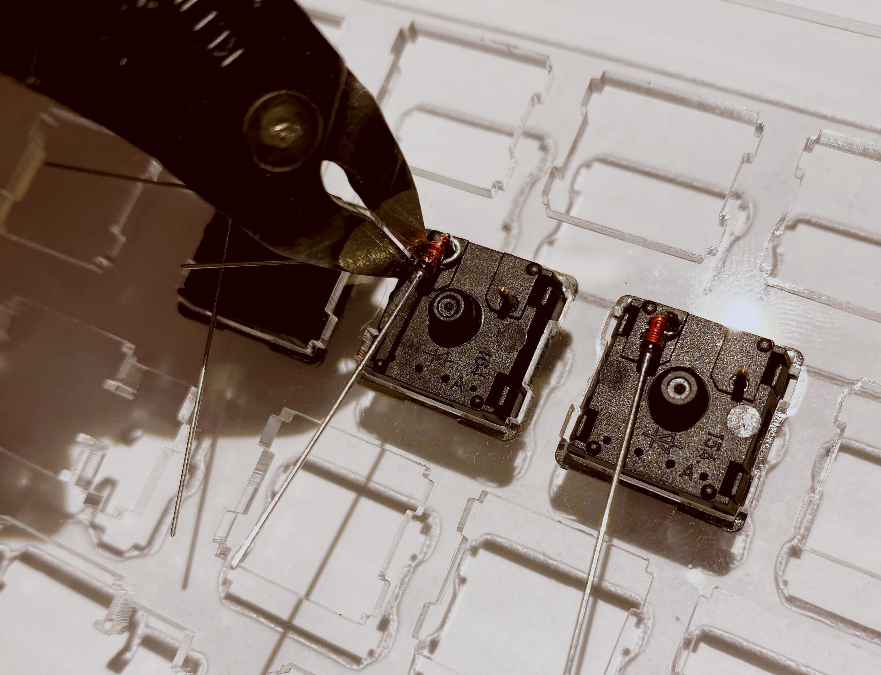
A diode only allows current to flow in one direction, and has a black band visual indicator on the diode to indicate which direction the current will flow. Current will flow from the Anode (+) side of the diode towards the black band, which is the Cathode (-) side of the diode.
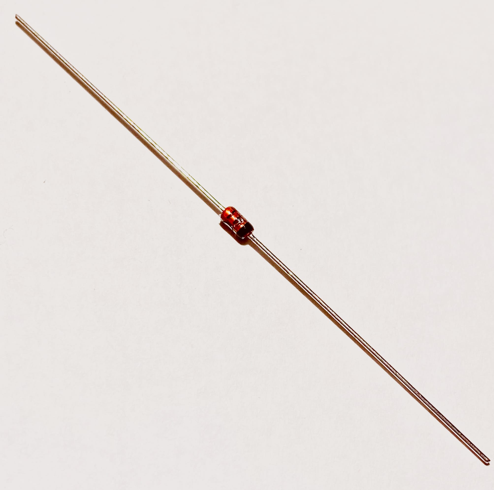
For the purposes of our keyboard, we need to ensure that the current flows from the top-left pin on the keyboard down to the row wire. This means we have to install our diodes with the black band facing towards the bottom of the key switch.
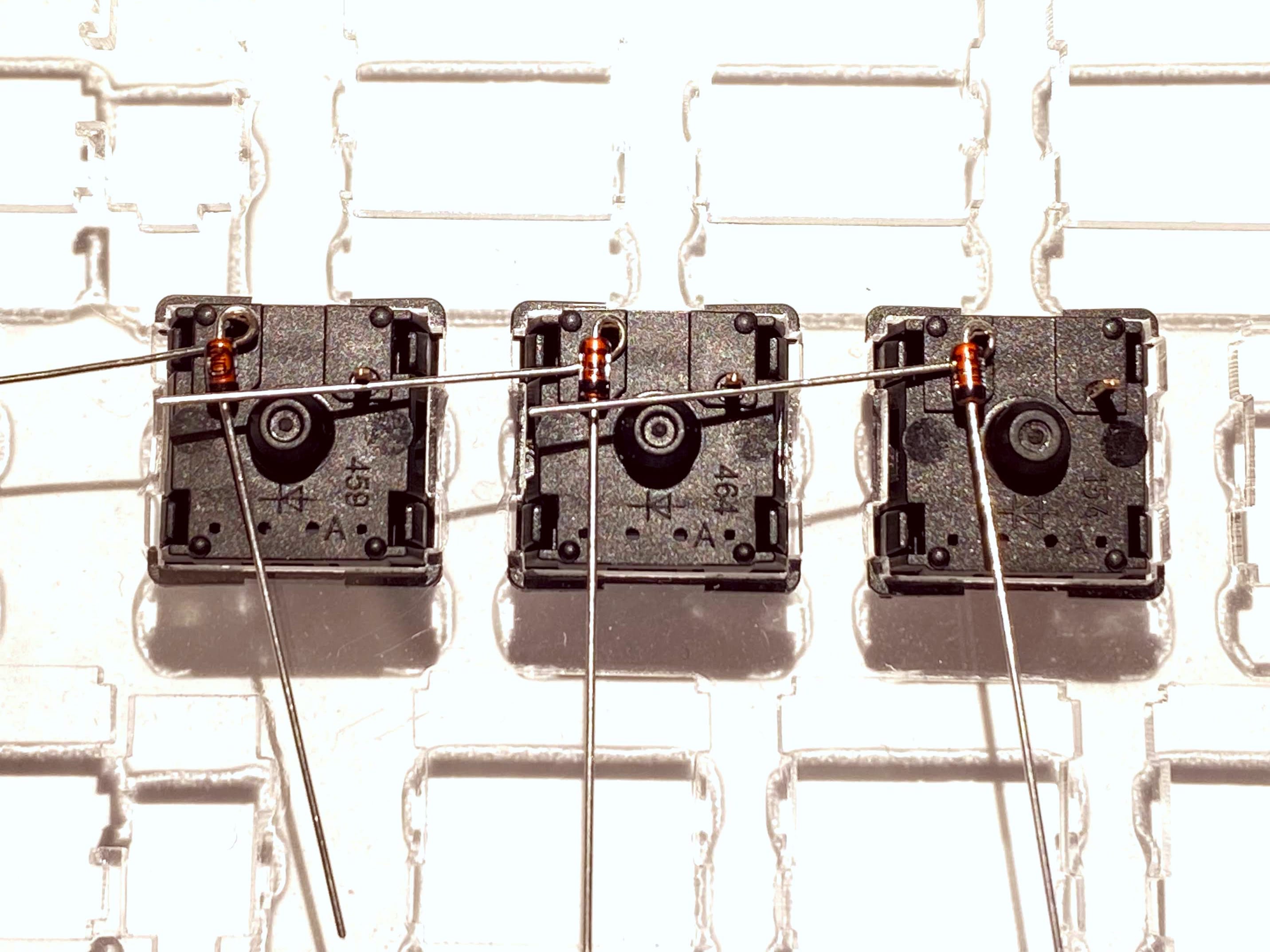
Taking inspiration from A modern handwiring guide - stronger, cleaner, easier , we will be creating a loop on the Anode (+) side of the diode which will soon be placed on the top-left pin of our key switch.
To get started, take a diode and bend the Anode lead in half at the joint where the lead leaves the body of the diode. Simply push the lead where it meets the body of the diode until the lead has been bent in half.
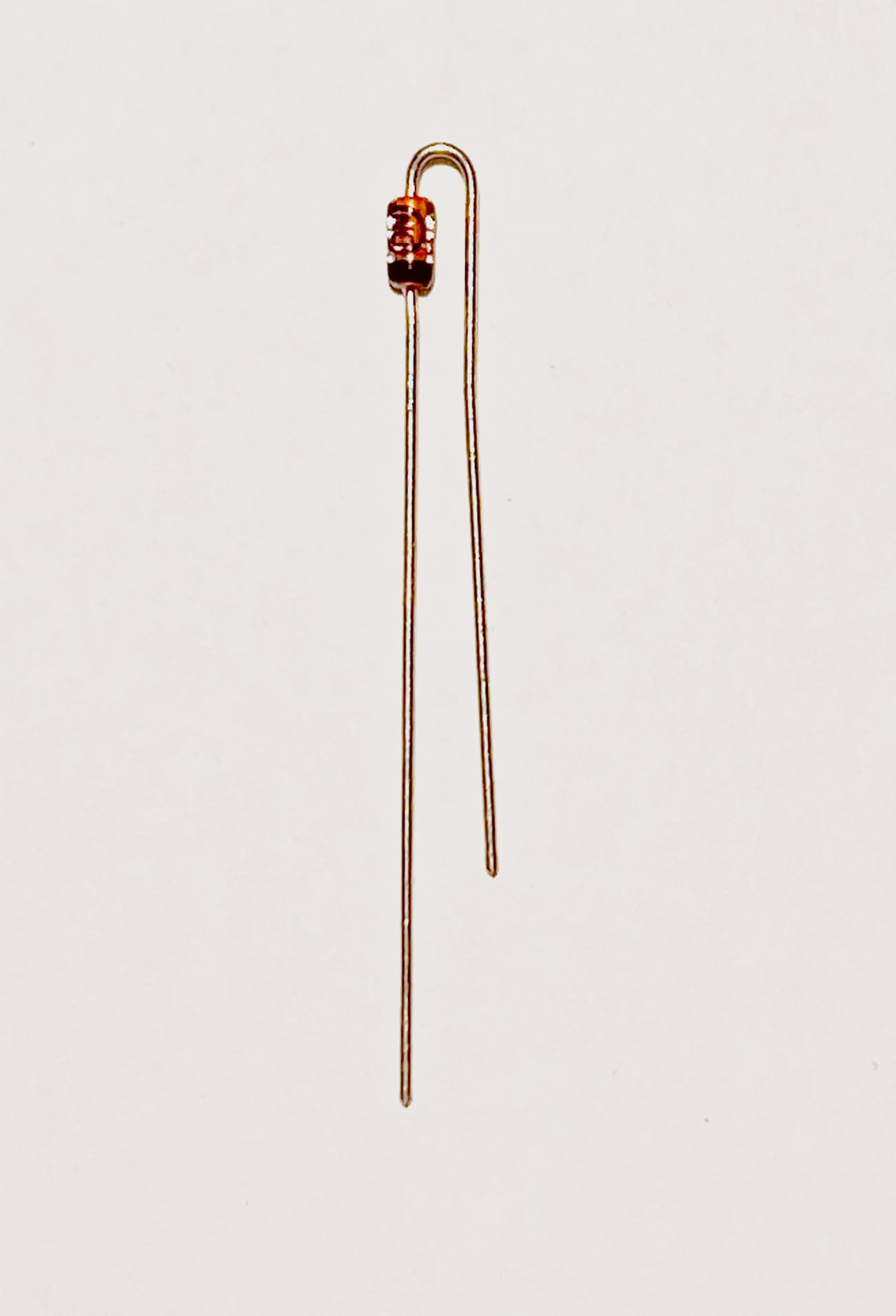
Now take the bent lead and push it under the body of the diode until it forms a small loop. You’ll want the leads of each diode to form a 90 degree angle.
You’ll have to repeat this process for all diodes. Once you get the hang of it, the work goes pretty quickly. Put on a podcast or some music, zone out and bend diodes!
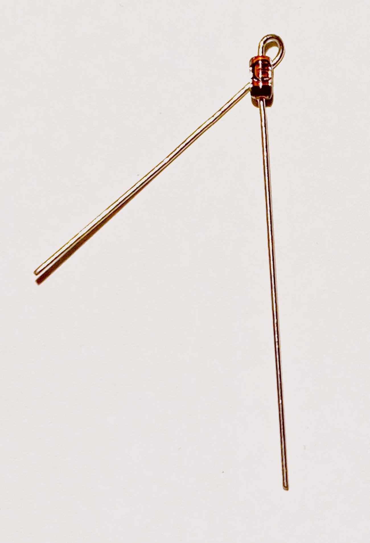
Once you have the diodes prepared, you’re now ready to attach and solder them to the key switches.
Place the loop on your diode over the top-left pin of each key switch. You can use the still-long leads to stabilize the diode, helping to ensure each diode is attached securely.
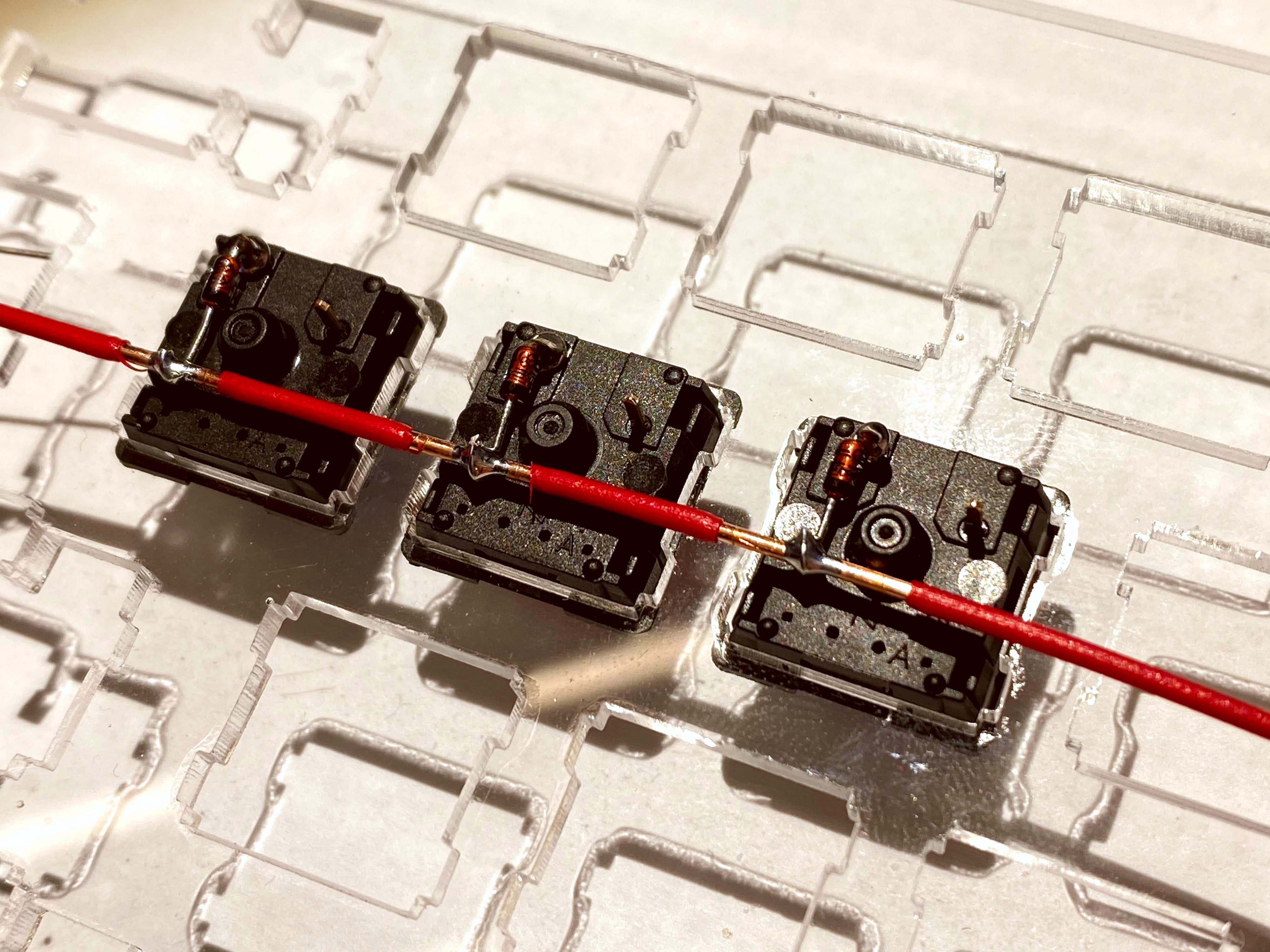
Row Wire Installation
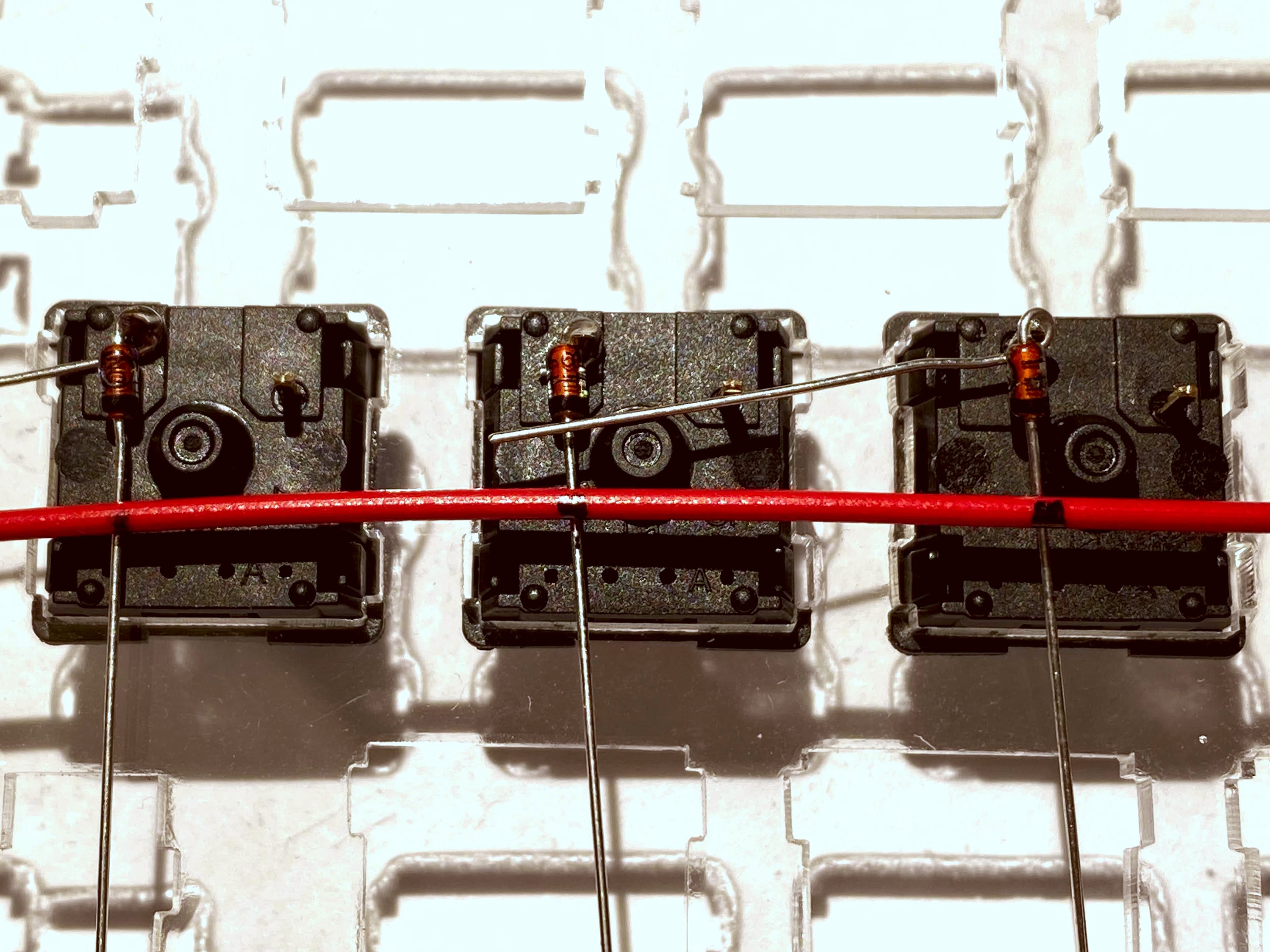
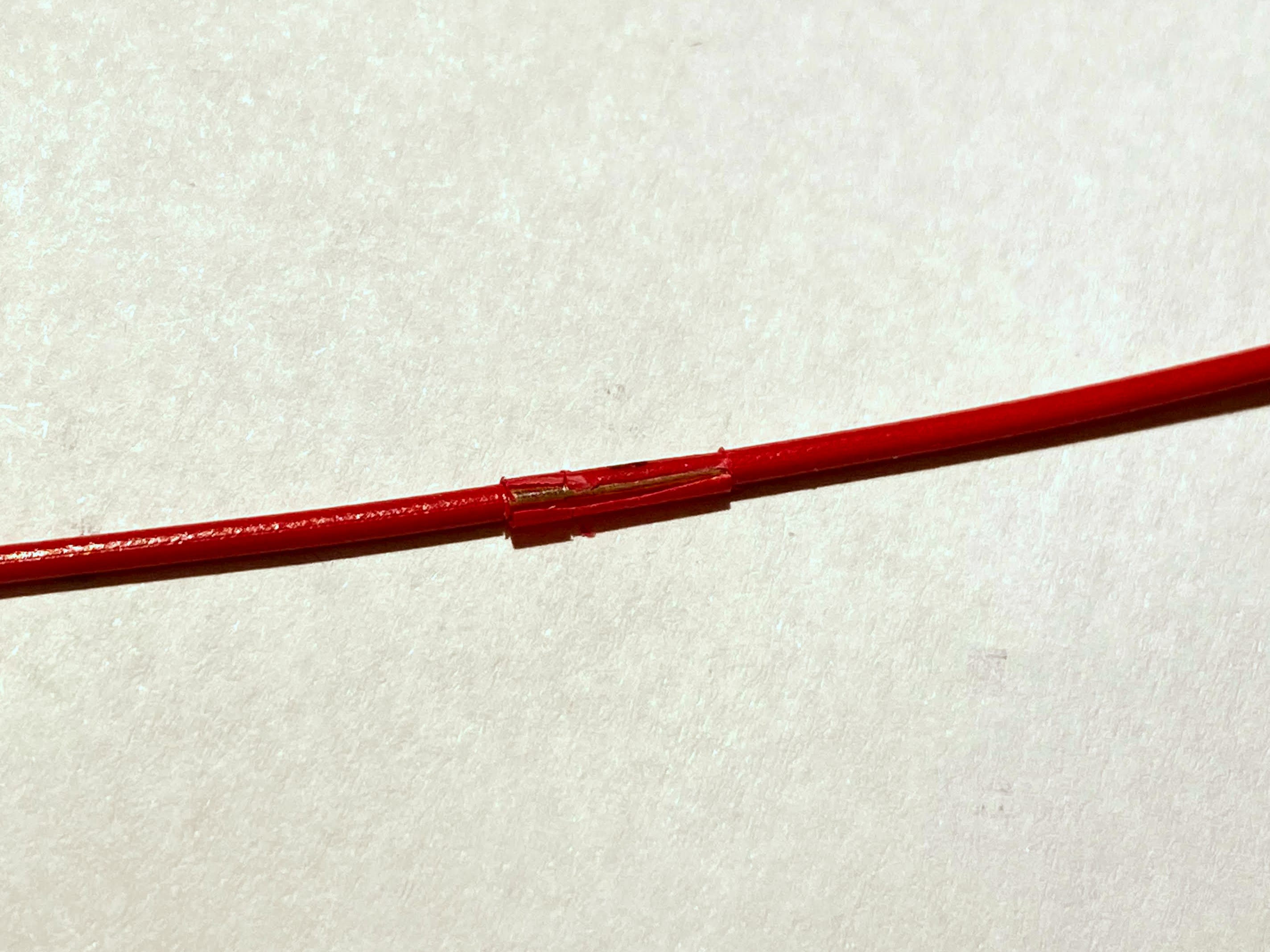
When you have all of the diodes installed and soldered, it’s time to install the wires which make up the rows for our keyboard matrix. I would recommend solid core wire, 18 gauge or lighter. For this design I used 18 gauge solid core wire with multicolor insulation. I stripped a small part of the insulation where it was soldered to the key switch, to preserve as much of the colored insulation as possible.
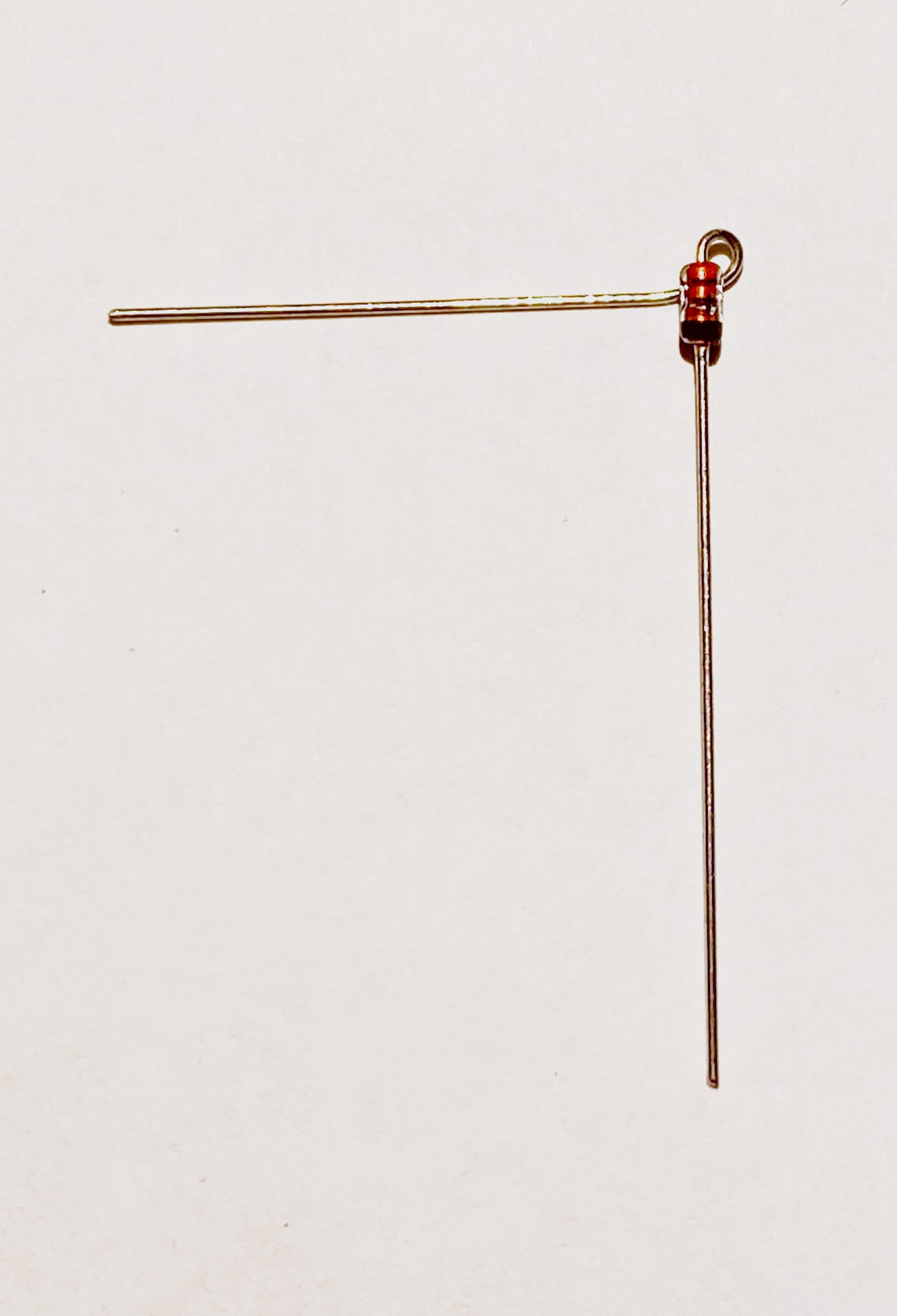
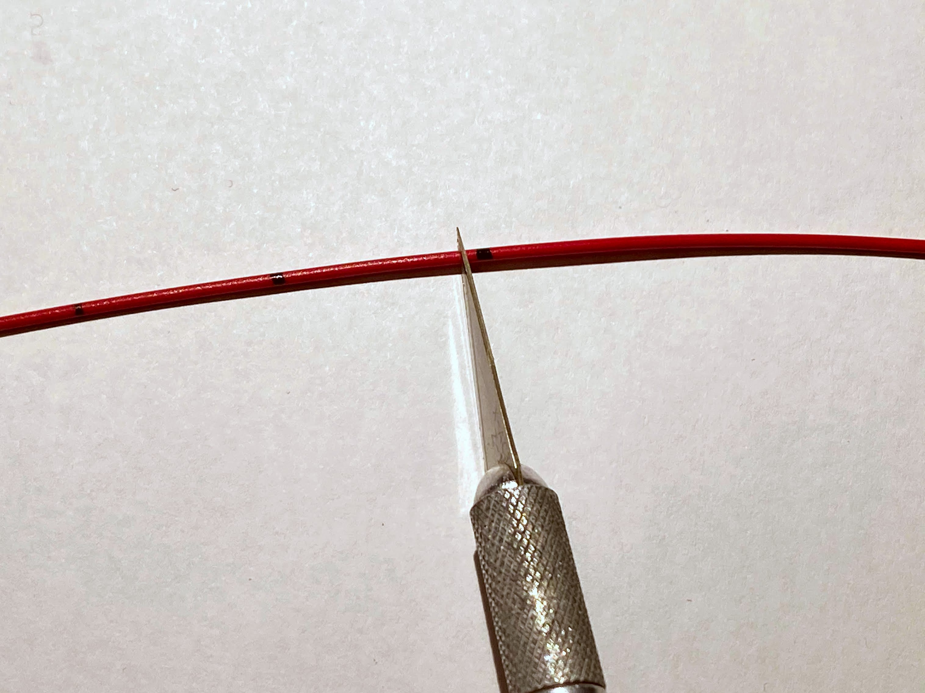
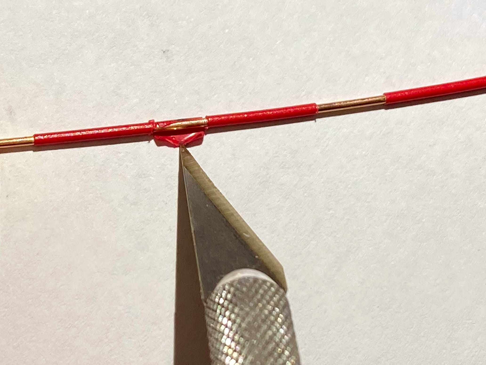
First I laid the row wire on top of the still-long diode leads, marking the row wire where a diode will be soldered
I then took an X-Acto knife to score and remove a small portion of the insulation
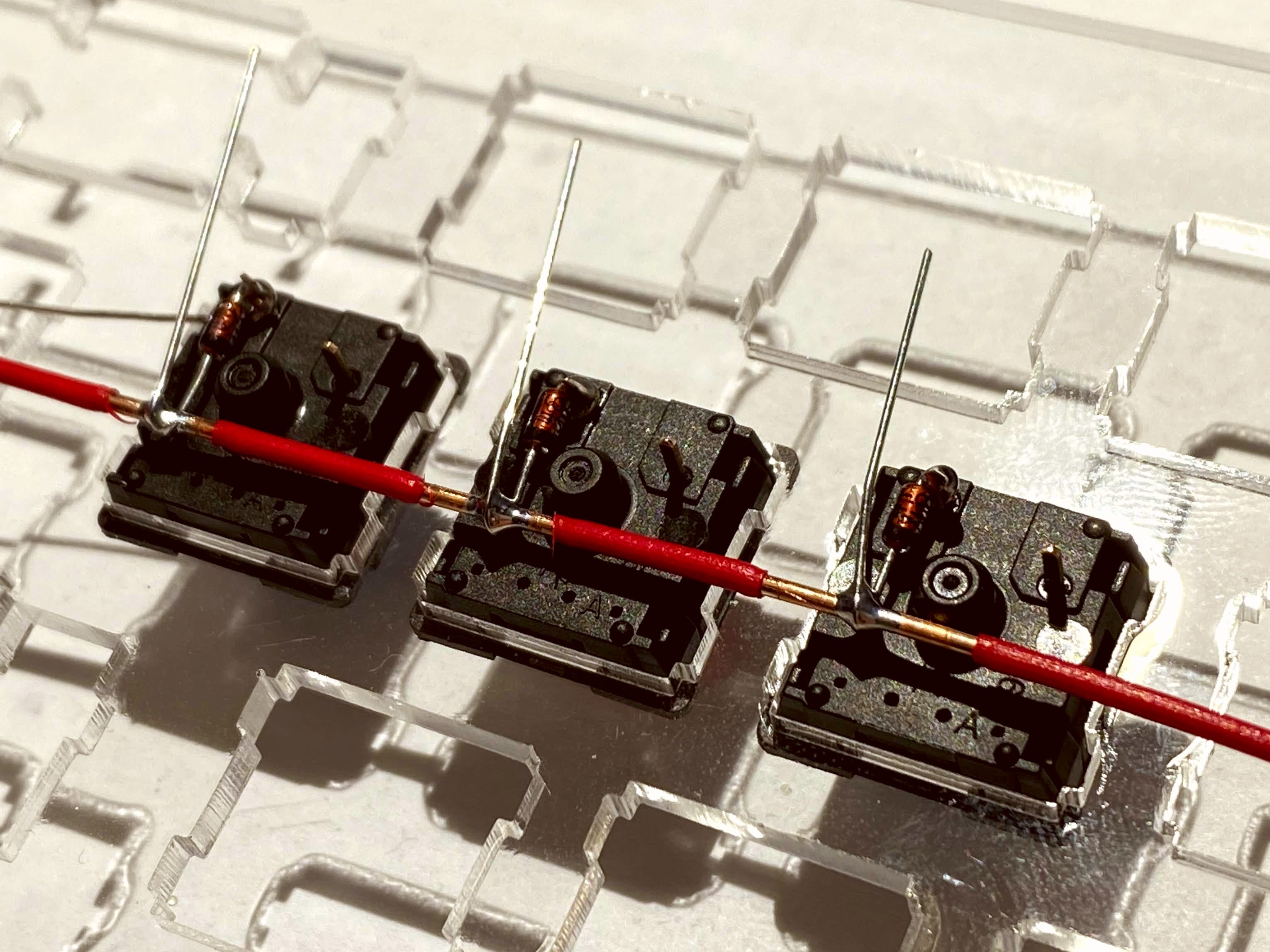
Once you have the insulation from your row wires stripped, place the wire on top of the diode leads and wrap the lead around the exposed part of your row wire
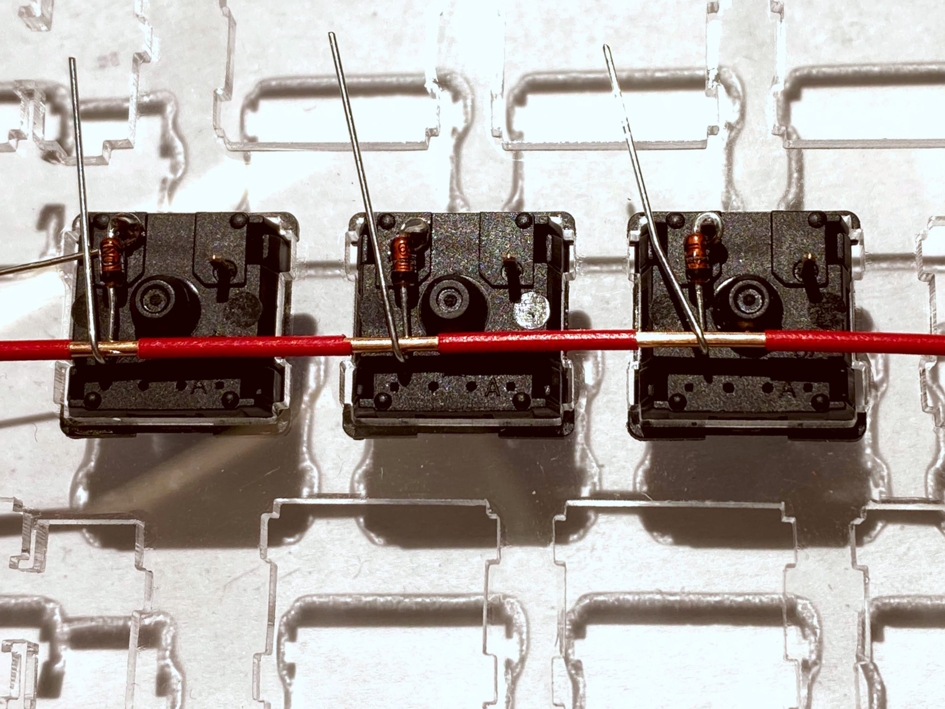
Once your row wires are installed, and diode leads are wrapped around, solder and clip the leads to be flush.
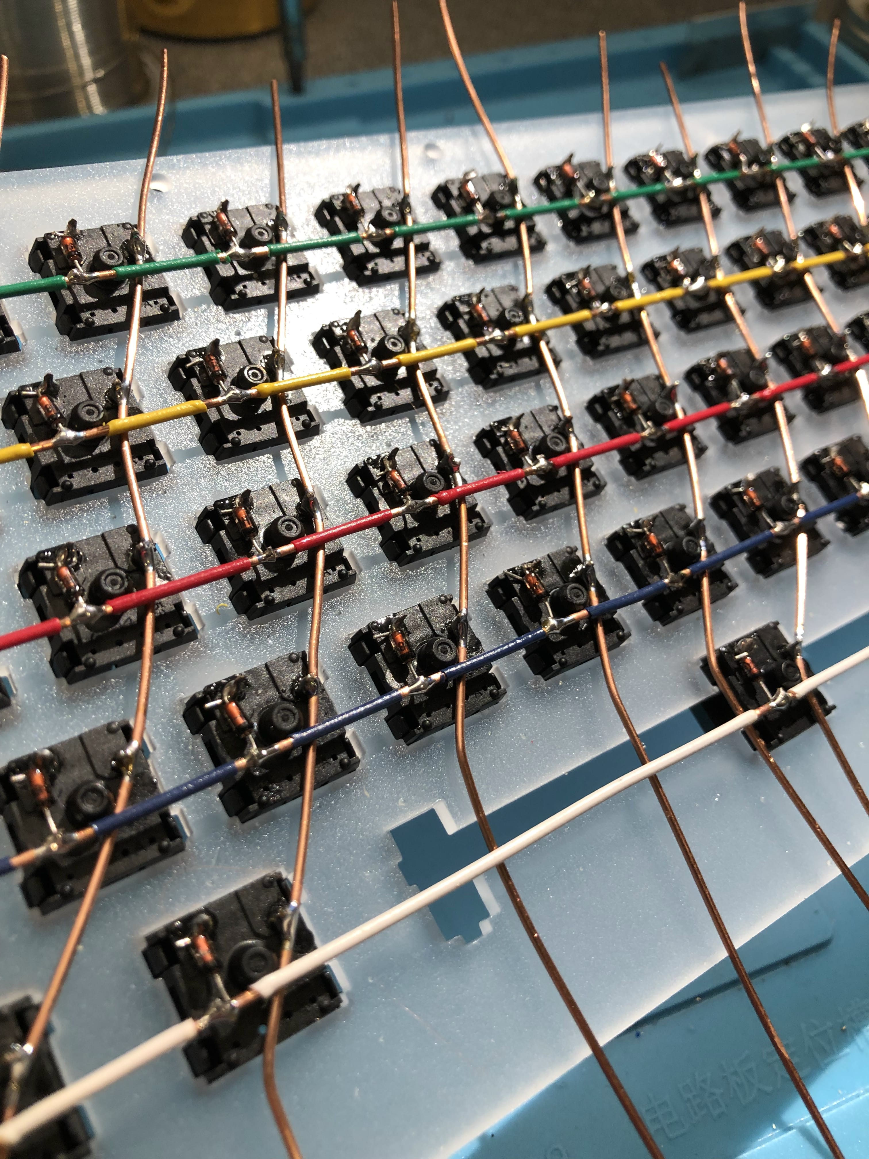
Column Wire Installation
When you have all of the row wires installed and soldered, it’s time to install the wires which make up the columns for our keyboard matrix. Again here I would recommend solid core wire, 18 gauge or lighter.
Take a single column wire, feed it under the row wires and solder it to the right side pin on each key switch for each column of your keyboard. The routing of your column wires will be dictated by the design of your keyboard, so there’s not a standardized way to do this. Take some time and think about the most logical way to represent “columns”, and route your column wires based upon that representation. When all column wires have been soldered in place, you can trim them to length.
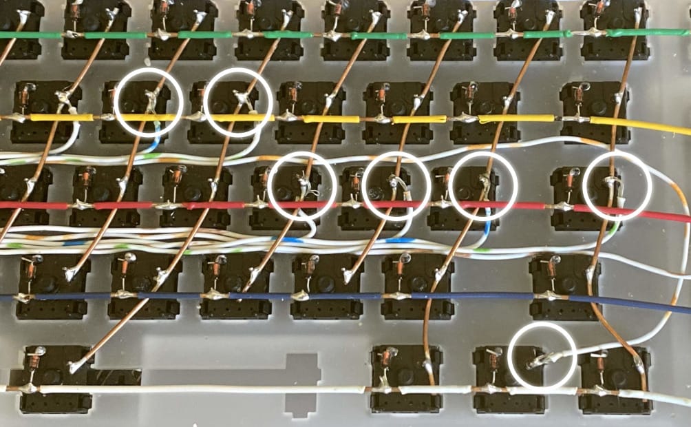
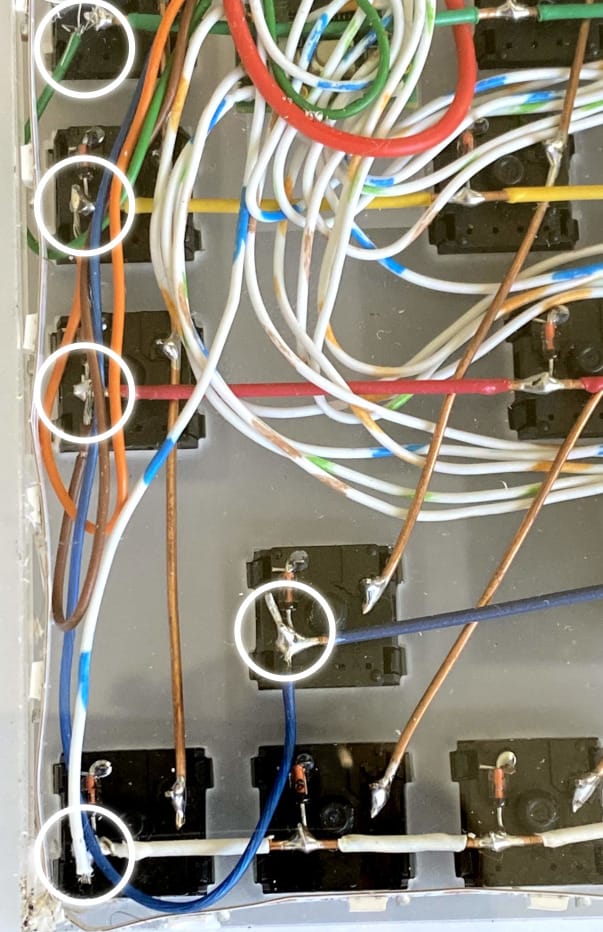
Connecting the Microcontroller
Once you have both the rows and columns wired and soldered to the key switches, it’s now time to wire everything to the microcontroller. Be forewarned, this is the most tedious part of this entire project. You’ll need to plan for, route and solder many, many wires. You’ll need to plan for (number of rows + number of columns) wires, and the same number of inputs on your microcontroller. This keyboard has 5 rows and 17 columns, for a total of 22 microcontroller wires and pins.
A number of people have used a ribbon cable to connect the matrix to the microcontroller, in this project I used the individual wires from an old network cable.
Regardless of the type of cable, you’ll need to solder one wire to every row, and one wire to every column. Where you solder the cable doesn’t really matter, but you do need to have something connected to each wire and column.
As a final challenge, you need to keep track of which microcontroller pin is connected to which wire for each row and column. That information will be used later when configuring QMK.
LED Installation
The LED Installation for this keyboard is very simple. WS2812-based LEDs utilize three connections, +5V, Ground and Data. Connect your microcontroller’s 5V Pin to 5V on your lighting strip, Ground to GND and a free data pin to Data In on your lighting strip.
In this keyboard I simply hot glued the LED strip around the perimeter of the keyboard.
Concluding the Hardware Build
Aside from troubleshooting, the hardware portion of this build is complete! You should spend some time testing your solder connections with your multimeter using it’s continuity mode. You should see continuity across the entire column, across the length of each row and from key switch to key switch.
QMK Keyboard Software Configuration
For this project I’m using the excellent open source QMK firmware to drive the keyboard and interface with my PC. The documentation is excellent, so I’m just providing a brief tl;dr for how to get QMK configured.
- Download and install QMK
- Generate a new keymap for your keyboard
qmk new-keymap -kb <keyboard-name>- You should now have a new directory under
$qmk_install_dir/keyboards/ - As an example, I now have
~/src/qmk_firmware/keyboards/televideo2k
cdinto your keyboard directory
config.h
With your favorite editor, open and edit
$qmk_install_dir/keyboards/<keyboard-name>/config.h- This is the file which defines the low-level configuration for our keyboard. At a minimum you will need to specify
MATRIX_ROWSMATRIX_COLUMNS,MATRIX_ROW_PINS,MATRIX_COL_PINSandDIODE_DIRECTIONMATRIX_ROWSis the number of rows we wired for this keyboardMATRIX_COLSis the number of columns we wired for this keyboardMATRIX_ROW_PINSis an array of the microcontroller input pins your rows are wired intoMATRIX_COL_PINSis an array of the microcontroller input pins your columns are wired intoDIODE_DIRECTIONis the direction our diodes are pointing. For this keyboard, our diodes are pointing from our columns to our rows
- Review the
documentation
for detail on the remaining configuration options within this file. The additional configuration options you’re most likely interested in are
MANUFACTURER,PRODUCTandDESCRIPTION; and if you have RGB lightingRGB_DI_PIN.
- This is the file which defines the low-level configuration for our keyboard. At a minimum you will need to specify
For reference, my config looks like:
  #ifndef CONFIG_H
  #define CONFIG_H

  #include "config_common.h"

  /* USB Device descriptor parameter */
  #define VENDOR_ID       0xFEED
  #define PRODUCT_ID      0x0000
  #define DEVICE_VER      0x0001
  #define MANUFACTURER    Ben Chapman
  #define PRODUCT         Televideo2K
  #define DESCRIPTION     Televideo Year 2000+

  /* key matrix size */
  #define MATRIX_ROWS 5
  #define MATRIX_COLS 17

  /* key matrix pins */
  #define MATRIX_ROW_PINS { D1, D0, B7, B3, B2 }
  #define MATRIX_COL_PINS { C6, C7, D3, D5, D4, F0, F1, F4, F5, F6, F7, B6, B5, B4, D7, D6, D2 }

  /* COL2ROW or ROW2COL */
  #define DIODE_DIRECTION COL2ROW

  ... snip ...

  /* RGB Backlighting configuration */
  #define RGB_DI_PIN B1
  #ifdef RGB_DI_PIN
  #define RGBLIGHT_ANIMATIONS
  #define RGBLED_NUM 51
  #define RGBLIGHT_HUE_STEP 8
  #define RGBLIGHT_SAT_STEP 8
  #define RGBLIGHT_VAL_STEP 8
  #define RGBLIGHT_SLEEP
  #define RGBLIGHT_EFFECT_KNIGHT_LENGTH 5
  #define RGBLIGHT_EFFECT_SNAKE_LENGTH 6

  #endif

  #endif
rules.mk
rules.mk is used to inform QMK what files to build, and what features to enable.
With your favorite editor, open and edit $qmk_install_dir/keyboards/<keyboard-name>/rules.mk
- At a minimum you’ll need to review and possibly configure
MCU,ARCH,BOOTLOADERbased upon the microcontroller you’re using - Additionally, there are many other additional configuration options you can specify in this file. Review the documentation and configure as needed.
keymap.c
keymap.c is used to
define the key mapping
of your keyboard. The configuration within this file is what allows you to truly customize your keyboard.
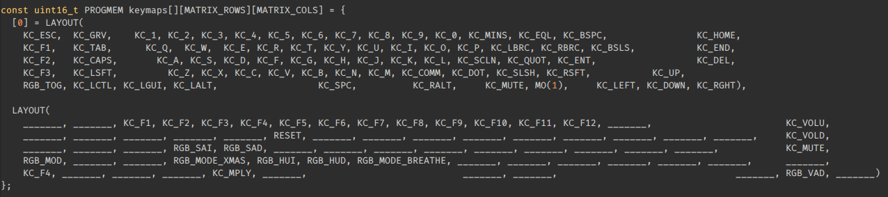
You’re looking for a line starting with const uint16_t PROGMEM keymaps[][MATRIX_ROWS][MATRIX_COLS] = {[0] = LAYOUT(
This is the configuration which defines what each key press does. When a key switch is pressed at location MATRIX_ROW x and MATRIX_COLUMN y send this keycode to the computer. While most people will have a standardized QWERTY, DVORK or COLMAK layout, you can customize it to your liking.
keymap.c is also where you define
QMK layers
. A layer effectively allows for your keyboard to have different “keys” at different times. For example, think of the ! symbol. On most keyboards ! is located on the same key as a 1, and you are able to type the ! by pressing and holding the SHIFT or ⇧ key. In this example, the 1 keycode is on Layer 1, and ! is on Layer 2. You invoke the functionality of Layer 2 by pressing and holding the modifier key SHIFT ⇧.
With QMK layers, you can provide the same functionality, but supercharged. As an example, on my keyboard, I do not have physical Function keys. I do however have QMK layer which transforms my physical number keys into F1 - F12 with a layer. I hold the modifier key and 1 which sends an F1 keycode to the computer. Modifier key and 5 for F5, etc.
In keymap.c you will have to represent all keys present on your keyboard, even if you don’t plan to use them. The visual formatting of this file does not matter to QMK, so it’s suggested that you attempt to visually format it to represent the physical appearance of your keyboard. This makes customization and modification of this file much easier.
As an example, my keymap.c looks like:
Once configured to your liking, save this file and try to compile QMK:
cd $qmk_dir
make <keyboard_name>:default
If all goes well, you’ll receive status output like the following:
QMK Firmware 0.8.103
Deleting .build/ ... done.
QMK Firmware 0.8.103
WARNING: Some git submodules are out of date or modified.
 Please consider running make git-submodule.

Making televideo2k with keymap default

avr-gcc (GCC) 5.4.0
Copyright (C) 2015 Free Software Foundation, Inc.
This is free software; see the source for copying conditions.  There is NO
warranty; not even for MERCHANTABILITY or FITNESS FOR A PARTICULAR PURPOSE.

Compiling: keyboards/televideo2k/televideo2k.c  [OK]
Compiling: keyboards/televideo2k/keymaps/default/keymap.c  [OK]
Compiling: quantum/quantum.c  [OK]
Compiling: quantum/keymap_common.c  [OK]
Compiling: quantum/keycode_config.c  [OK]
Compiling: quantum/matrix_common.c  [OK]

... snip ...

Linking: .build/televideo2k_default.elf  [OK]
Creating load file for flashing: .build/televideo2k_default.hex  [OK]
Copying televideo2k_default.hex to qmk_firmware folder [OK]
Checking file size of televideo2k_default.hex [OK]
 * The firmware size is fine - 30474/32256 (94%, 1782 bytes free)
If you do receive errors, go back and review your keymap.c file. It’s very easy to forget a comma or forget to include one of your keys.
Once you have a good build for your keyboard, it’s time to flash it to the microcontroller . There’s a lot of variability here, so I would recommend reading through the documentation specific to your setup and microcontroller.
Testing Your Keyboard
Once you have everything configured, and QMK has been flashed to your microcontroller, it’s time to test your keyboard.
Connect your keyboard to your PC via USB. Assuming QMK was flashed successfully the keyboard should be automatically detected as a USB HID (Human Interface Device).
On macOS or Windows, you can use
QMK Toolbox
to print the output from your key presses. On Linux you’ll need to use the xev utility, which is provided with x11-utils and likely already installed on your computer.
$ xev |egrep "(KeyPress|KeyRelease|XLookupString)"

KeyPress event, serial 40, synthetic NO, window 0x5a00001,
    XLookupString gives 1 bytes: (61) "a"
KeyRelease event, serial 40, synthetic NO, window 0x5a00001,
    XLookupString gives 1 bytes: (61) "a"
KeyPress event, serial 40, synthetic NO, window 0x5a00001,
    XLookupString gives 1 bytes: (73) "s"
KeyRelease event, serial 40, synthetic NO, window 0x5a00001,
    XLookupString gives 1 bytes: (73) "s"
KeyPress event, serial 40, synthetic NO, window 0x5a00001,
    XLookupString gives 1 bytes: (64) "d"
KeyRelease event, serial 40, synthetic NO, window 0x5a00001,
    XLookupString gives 1 bytes: (64) "d"
KeyPress event, serial 40, synthetic NO, window 0x5a00001,
    XLookupString gives 1 bytes: (66) "f"
KeyRelease event, serial 40, synthetic NO, window 0x5a00001,
    XLookupString gives 1 bytes: (66) "f"
You’re looking to ensure the output from QMK Toolbox or xev matches what you’ve configured within QMK. If you press what you configured to be the “A” key, and QMK Toolbox or xev outputs “F”, you have a misconfiguration. Go back and review your configs. If you’re confident your QMK configuration is correct, it’s likely there is a mistake with the configuration of MATRIX_ROW_PINS or MATRIX_COL_PINS in config.h. Review the wiring of your keyboard matrix and validate the physical wiring matches your QMK configuration, and specifically which pins on your microcontroller are connected to which row or column.