Creating a Programmable Animated Display Using Arduino and FastLED
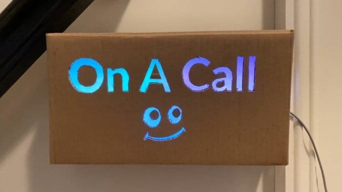
Table of Contents
For those who now spend a majority of the day on video conferences, it would be useful to have a way to let your family know you’re on a call, so that’s exactly what I did. I built a fun, programmable sign which automatically turns on when I’m on a call, and turns off when I’m free.
Limiting my social exposure outside of the house, I decided to build this sign using whatever materials I had on hand, which included a cardboard box, an ESP8266-based Arduino and some Neopixel-compatible WS2812B programmable LEDs.
Even though this is constructed from cardboard, the sign doesn’t look terrible. If I were to do this again, I‘d probably laser cut this sign from wood or build an edge-lit acrylic sign.
Hardware Needed
- An ESP8266-based Arduino micro controller
- Addressable LEDs (e.g. WS2812B or Neopixels )
- An enclosure of some type
Software Needed
- An IDE with Arduino support
- A Sign Template
- My Arduino code for this project
Enclosure Construction
Once you’ve found a suitable material to house your sign, you’ll need to figure out how to make it into a box.
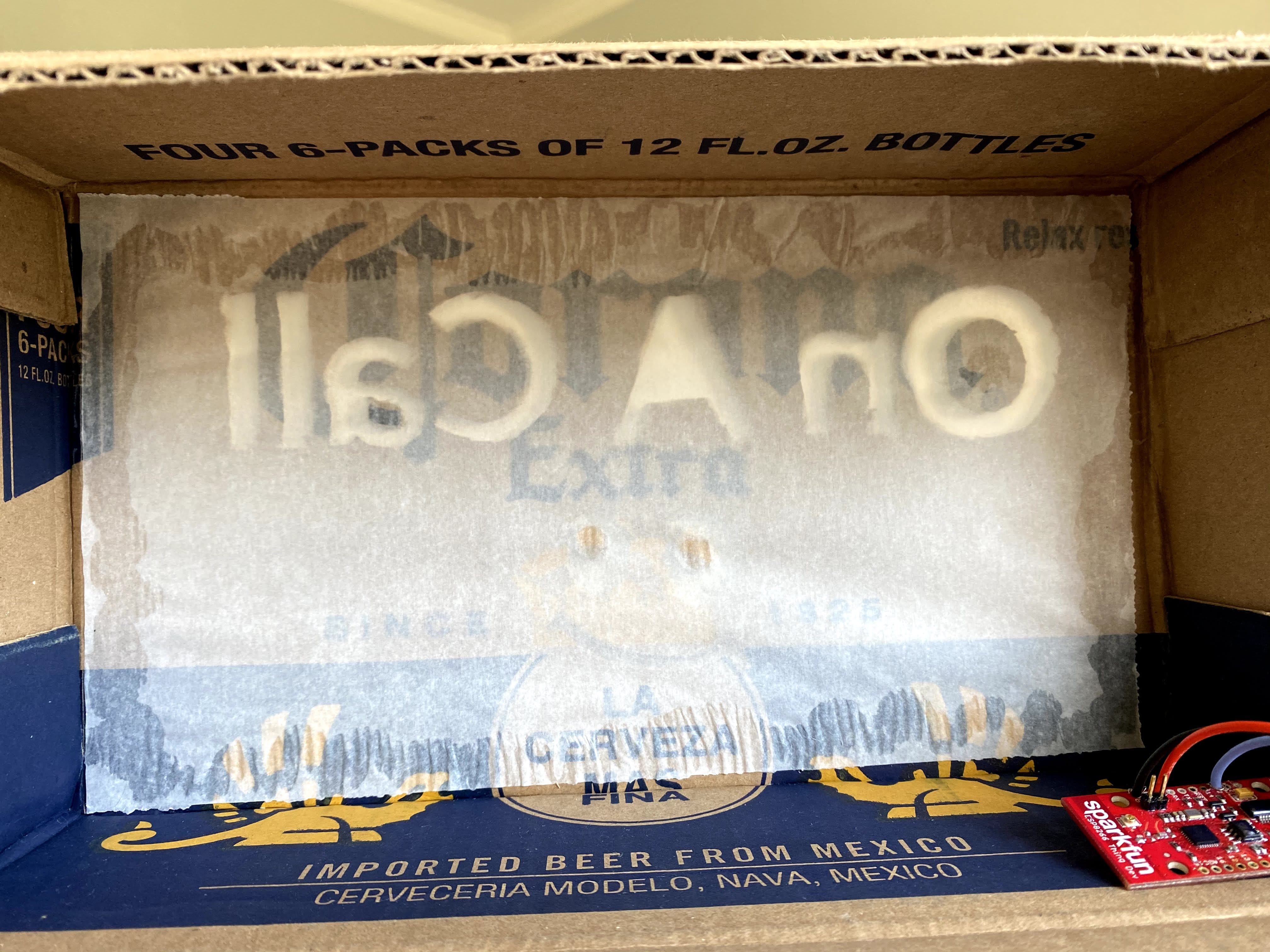
I used an old cardboard box, which I had on hand at home and which I was able to easily cut and fold into a smaller box.
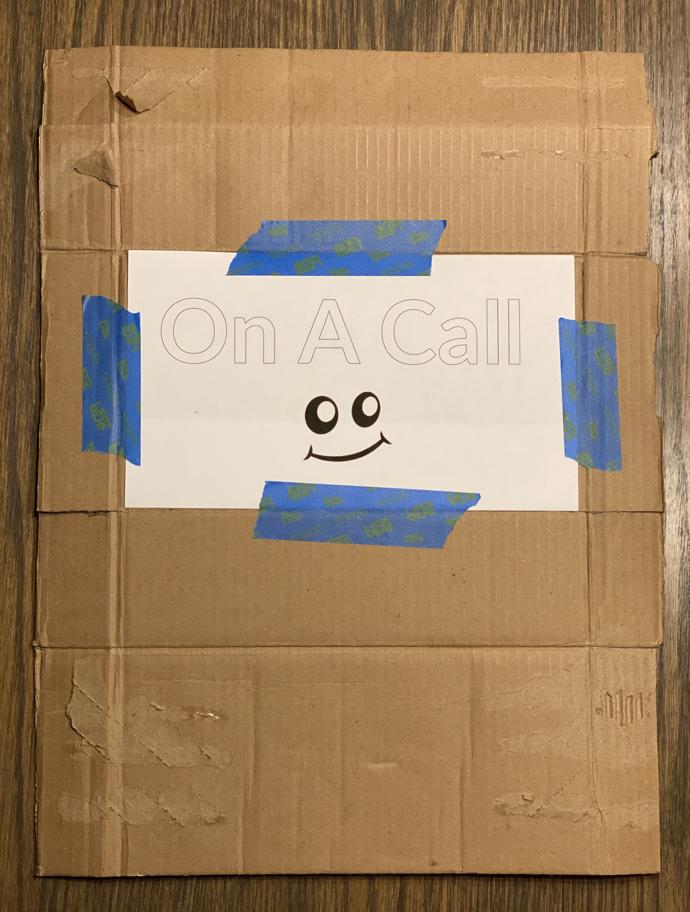
You’ll want to end up with something that has a front face of approximately 11.5 inches wide, and 6 inches tall (30 cm wide, 15 cm wide).
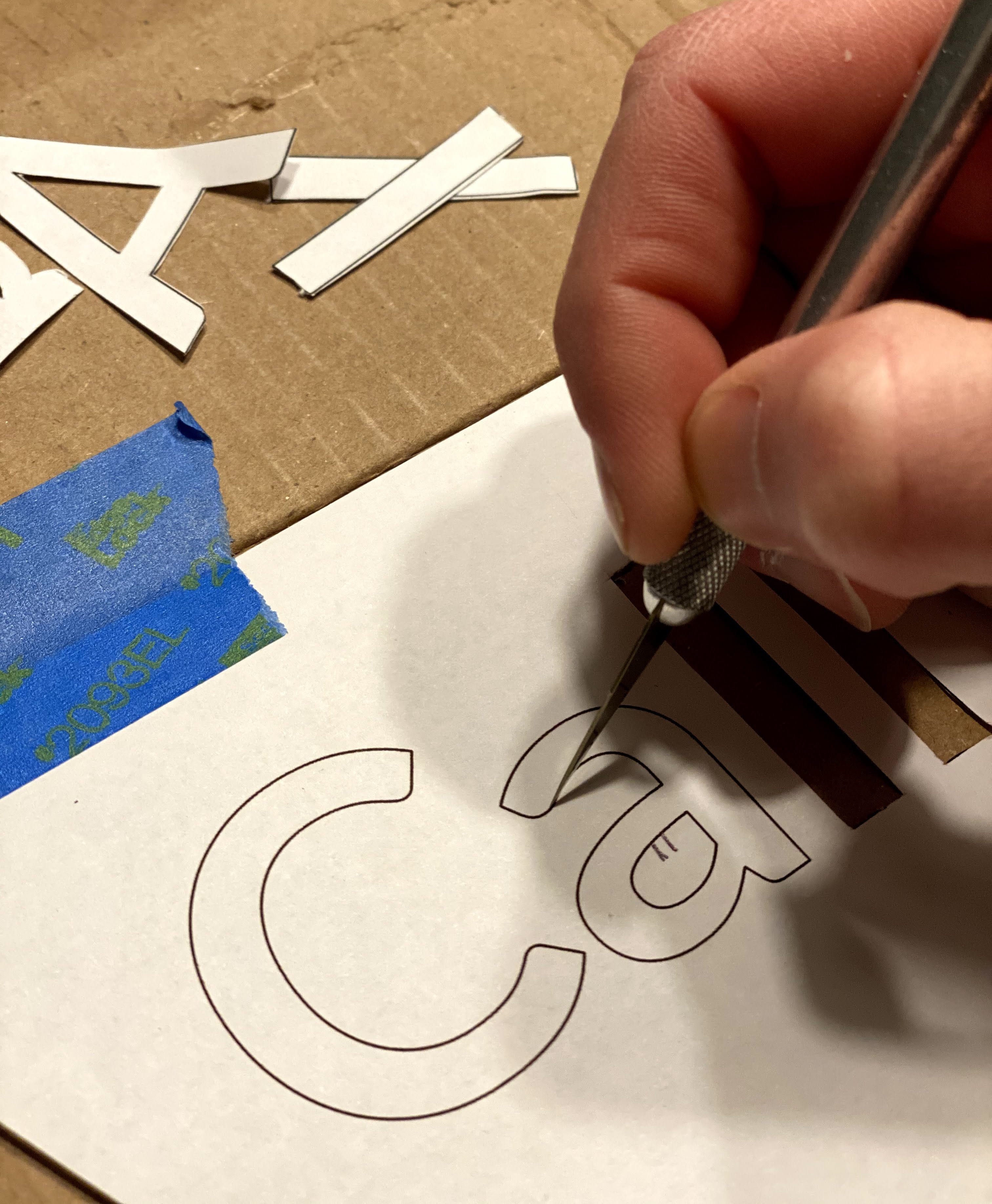
Once you have your enclosure built, print and then tape the sign artwork on the front face of the box. You’ll be using the outline of the artwork to cut through your enclosure. Be sure to save the middle parts of the letters like O and A, as you’ll need to glue them back in place later.
Using the outline of the letters and smiley face, carefully cut all the way through the cardboard. This will likely take several passes, take your time.
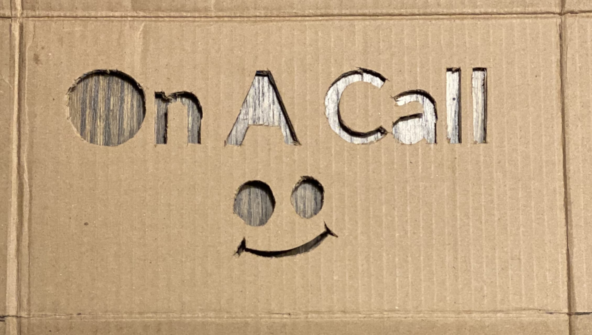
Now on the back face of your sign, you’ll need to affix some light diffusing material. I used parchment paper from the kitchen — a sheet of blank printer paper will also work fine, but will reduce the brightness of your finished sign.
Lighting Construction
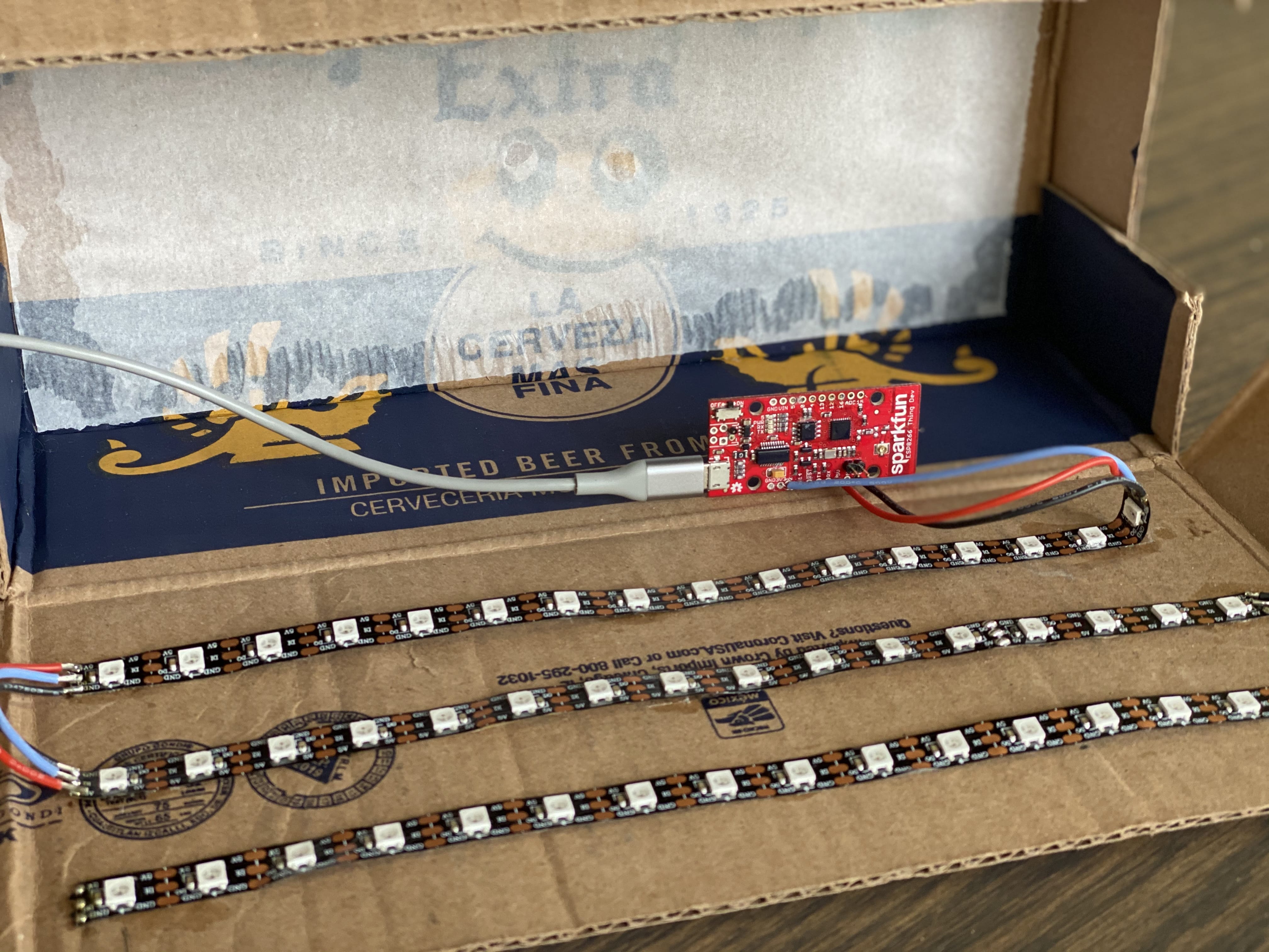
I’m using WS2812B (Neopixel) addressable lights for this project, so the lighting setup was pretty straightforward. I have three strips of 16 LEDs, glued to the back flap of my enclosure, all wired into a ESP8266-based micro controller which provides WiFi capabilities.
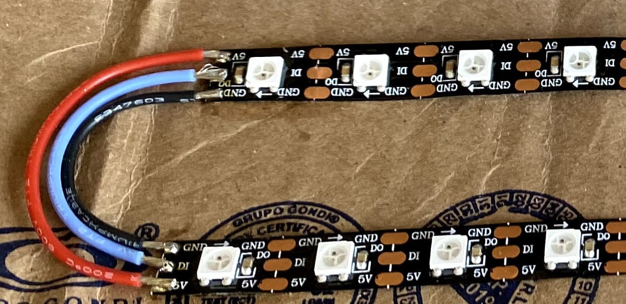
One of the really fun things about WS2812 addressable LEDs is you can cut the LED strip at any point along it’s length to customize for your specific need. Because of this, you’ll need to pay special attention to the markings on your specific WS21812 strips. You’ll be looking for an ➔ or some other indicator of the direction of both signal and power. Both power and data path begin at the head of a strip (connected directly to your micro controller), and continue down the length of that strip until there’s a break. The ➔ marking helps you to orient when dealing with multiple strips (as we have here).
When cutting these strips, you’ll need to solder the two halves back together as seen below.
To complete the lighting setup, you’ll need to provide +5V, Ground and a digital signal from your Arduino. In my example code I’m using Pin 2 , but any output pin will work and you can easily adjust the code to reference whatever pin you choose.
Let’s get the lighting party started
I’m using the FastLED library to drive the LEDs, and specifically some amazing demo code from Mark Kriegsman for the flashy effects. FastLED provides for a deep amount of customization, and with that comes a bit of a learning curve. I found it very useful to spend some time with the demo code Mark provided to better understand how FastLED works.
Arduino Web Server
Because we’re using a WiFi-enabled Arduino, the basic idea is to run a lightweight web server on the Arduino listening for HTTP requests which then enable or disable the lights.
The web server has two endpoints /status and /toggle. A GET request to /status will return the current status of the sign (on or off), and a GET request to /toggle will flip the state of the sign (on to off, or off to on). That’s all there is to it.
$ curl http://10.0.0.109/status
sign-off

$ curl http://10.0.0.109/toggle
1

$ curl http://10.0.0.109/status
sign-on
Finishing it up
Once you’ve got everything wired up and tested your LEDs, you can fold your enclosure, making it into a complete box. You should be able to power the Arduino and LEDs from the USB power input on your micro controller. At 5V input, each LED draws around 50mA at full brightness. In theory, if we were to power all 48 LEDs, at full brightness you would be pulling ~2.4A which far exceeds the capacity of most USB power bricks, so keep a close eye on power draw.