Supercharge Your IBM Model M Keyboard With QMK
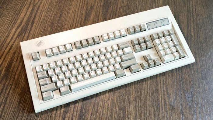
Table of Contents
The IBM Model M is unarguably one of the best keyboards ever manufactured. IBM’s buckling spring mechanism provides an audible and tactile typing experience that is seen as the benchmark for many keyboard enthusiasts. As a testament to their design, many original Model M’s are still in perfectly working order, and many are still in use as a day-to-day keyboard. You’re able to connect a vintage Model M to a modern computer through a simple PS/2 -> USB converter , and you’re off and typing.
What if you wanted to supercharge your Model M; provide capabilities that never originally existed? When is the last time you used the Scroll Lock key, how about Pause? Want to remap Caps Lock to something more useful, change the layout from QWERTY to COLMAK or DVORAK? Connect your Model M using a native USB connection? It turns out there’s a straightforward and non-destructive way to do this with a few hardware components and using Quantum Mechanical Keyboard .
Hardware Needed
IBM Model M keyboard
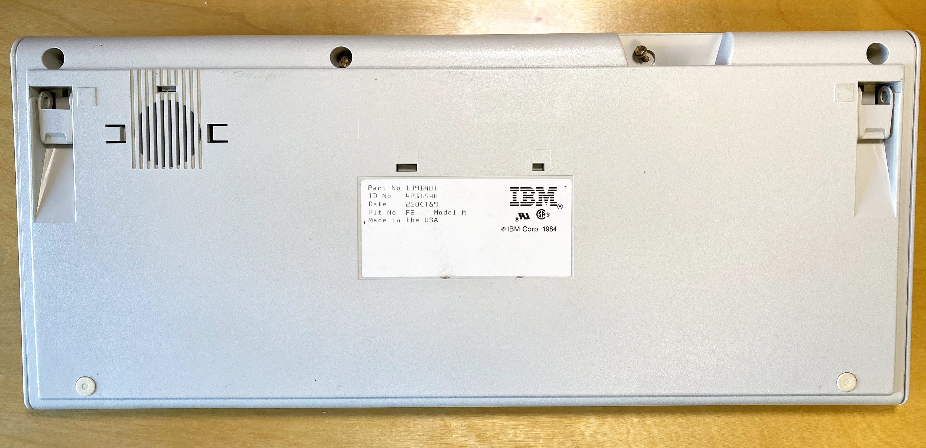
- The Model M version used for this project is part number 1391401, manufactured on the 25th of October, 1989. Any Model M manufactured by IBM or Lexmark should work for this project.
Optional Breadboard and hookup wire for prototyping

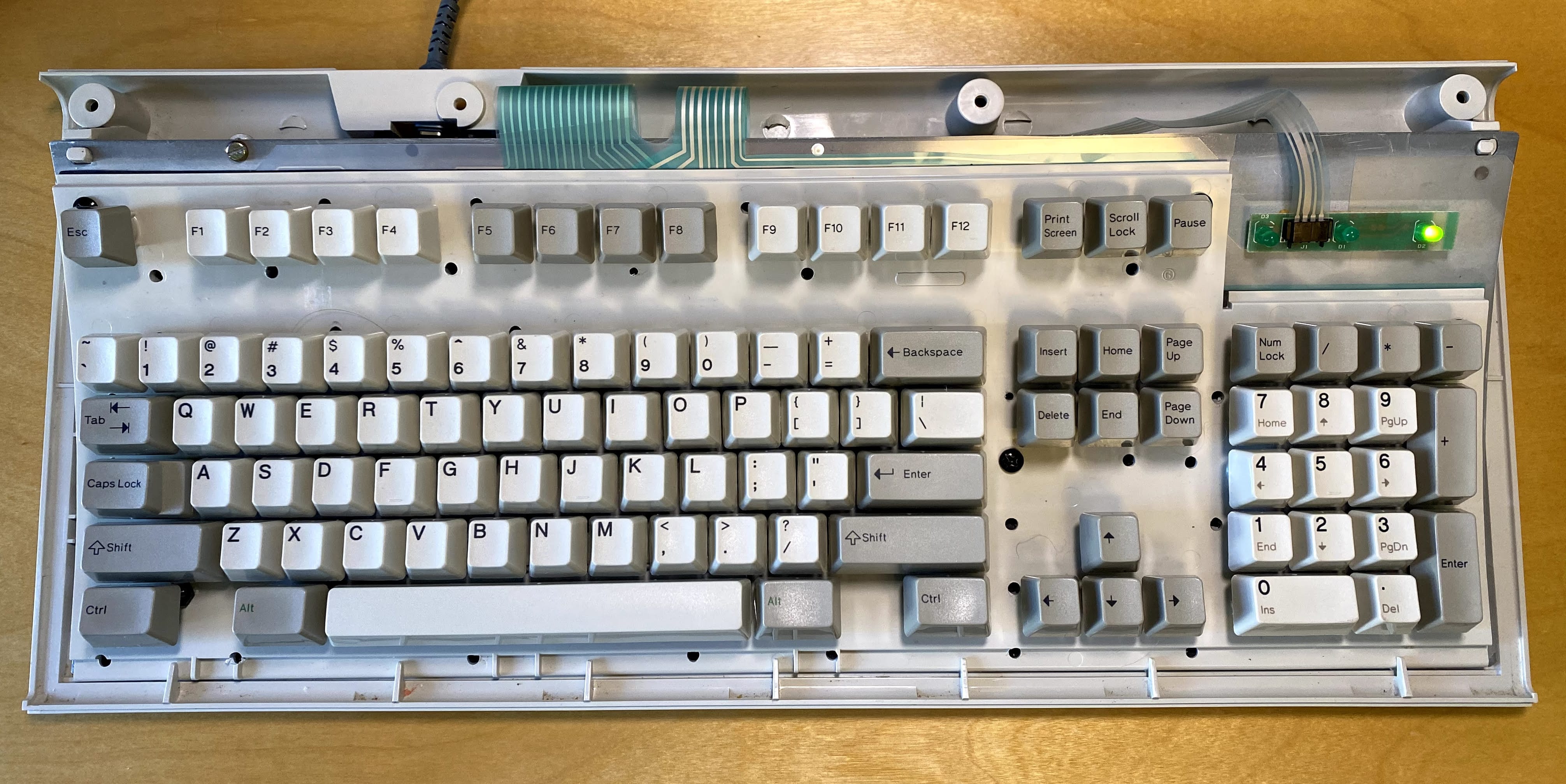
Sometime during the life of the Model M, the connections for the keyboard membrane (which transmits key presses to the controller) were changed. Earlier Model M keyboards had three flat flex cables, one for the keyboard’s rows, one for columns, and a separate cable for LEDs. Later models consolidated the cable carrying row signals with the LED cable, resulting two flat flex cables.
You need to know which keyboard you have before ordering these parts. The best way to figure this out, is to disassemble the keyboard, and count the number of flat flex cables present. If you have three flat flex cables, you have an older Model M, if you have two flat flex cables, you have a newer Model M.
If you have purchased, or plan to purchase a replacement membrane from Unicomp , those have two ribbon cables.
Where this process is different, I’ll refer to an older, and a newer Model M. My Model M is an older model with three ribbon cables, the photos here reflect that.
Older Model M:
Newer Model M:
Software Needed
- Quantum Mechanical Keyboard Firmware
(QMK)
- We will be using QMK to interface with and drive our keyboard
Keyboard Disassembly
To get started, we need to remove the keyboard’s inner assembly from the outer housing protecting the keyboard. This is a simple operation, requiring the removal of four 5.5 mm screws from the back of the keyboard’s housing.
Once you have the screws removed from the keyboard’s case, proceed to remove the top cover of the keyboard and carefully remove the two or three ribbon cables from the Model M’s controller. Now proceed to remove the keyboard from the case, and remove the original Model M controller from the bottom half of the case.
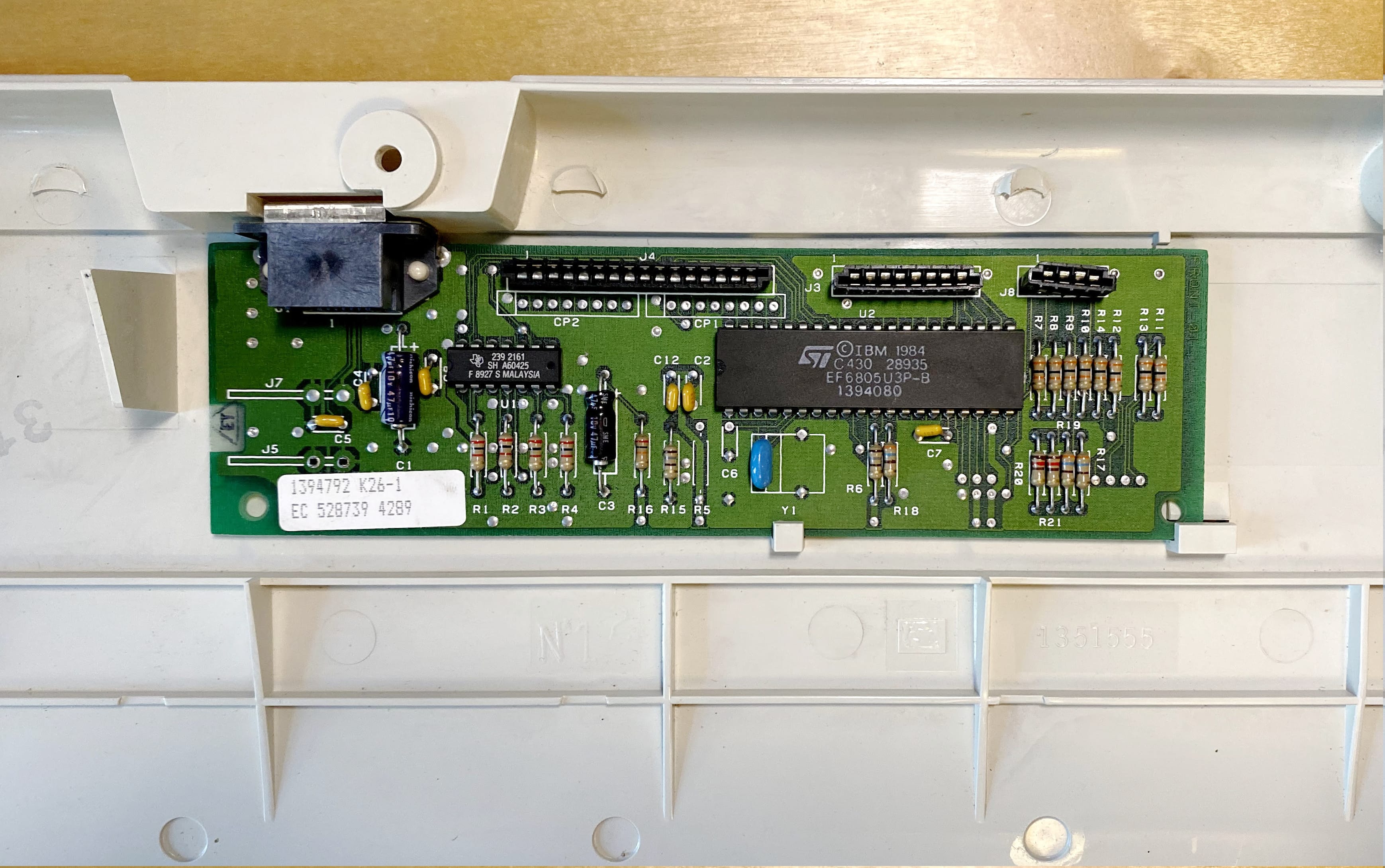
At this point you should have the top and bottom half of the Model M’s case, the keyboard plate and controller all as separate components. You can set aside the top and bottom halves of the case for re-installation later, and you can safely store the original Model M controller, as it’s no longer needed.
QMK Controller Assembly
One of the goals for this project was to integrate QMK into this keyboard in a non-destructive way. Taking inspiration from iw0rm3r’s previous work , this project looks to simplify the connection of the Model M’s keyboard matrix into the Teensy through reuse of the 16 pin flat flex connector for the keyboard’s columns, and the 8 or 12 pin flat flex connector for the keyboard’s rows, and optionally the 4 pin flat flex cabled used to drive the LEDs. This conveniently results in a simple build which integrates QMK into a IBM Model M.
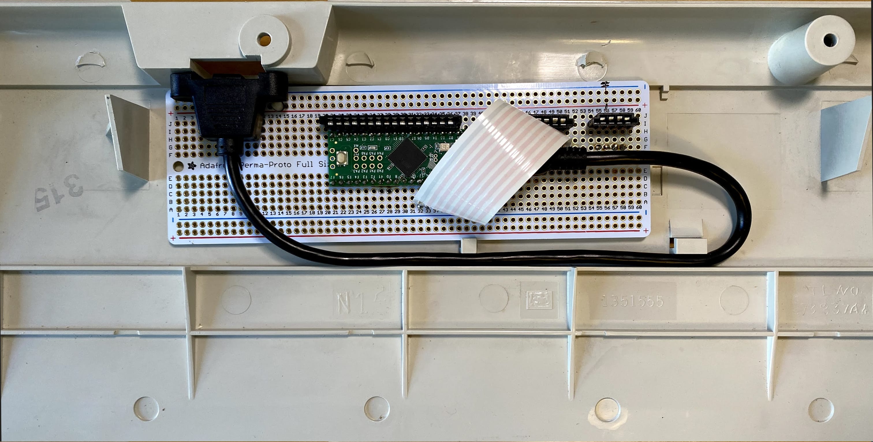
The final product will utilize a full-sized Adafruit Perma-Proto board, but it’s often helpful to assemble and test this new Model M controller using a breadboard.
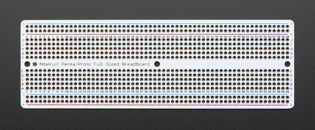
Alternatively, this is a straightforward build which should be safe enough to permanently connect to the Perma-Proto without much trouble. If you follow the instructions here, you should not run into any issues in getting this to work.
By using a Perma-Proto, we have plenty of room to work with and the niceties of a breadboard-like product which you can directly solder to. It also fits nicely into the Model M’s case without modification, making for a non-destructive enhancement to our keyboard.
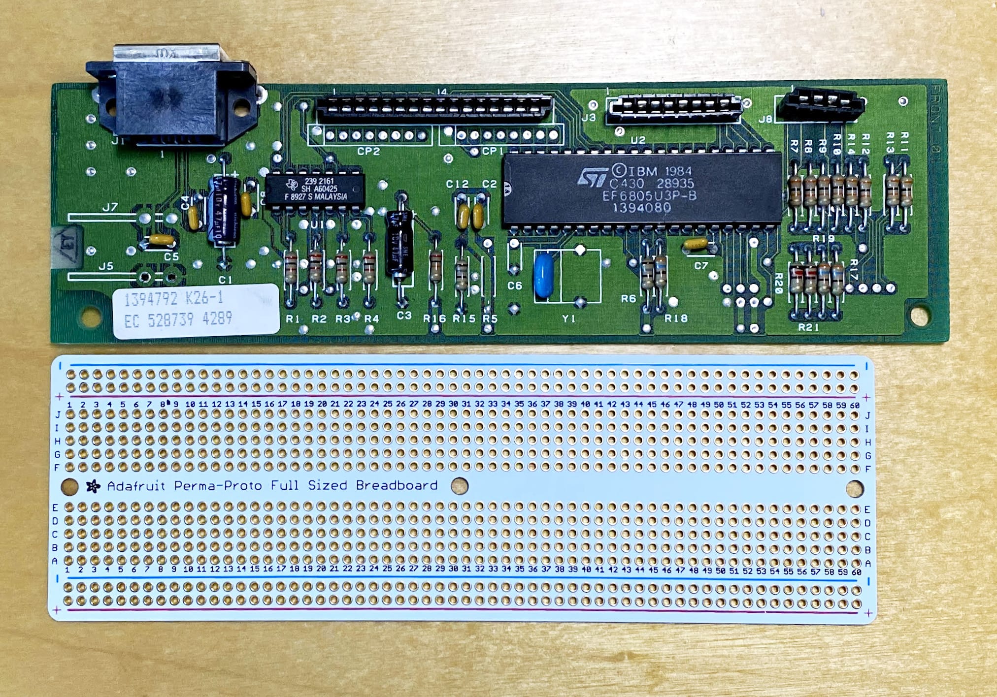
It turns out, the original Model M keyboard controller is almost the same size as a full sized breadboard, which allows for simple modifications to the Perma-Proto, and no modifications to anything original to the Model M. Nice.
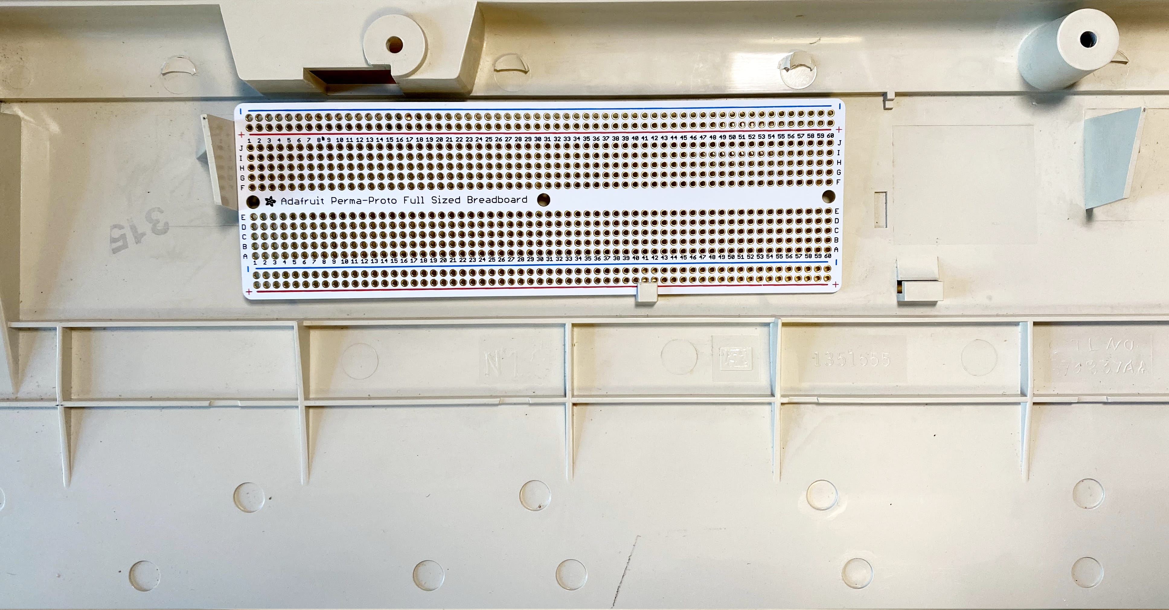
Fitting the Perma-Proto to the Case
We need to make some simple modifications to the Perma-Proto, allowing it to fit within the Model M’s case. We’ll begin by drilling the holes needed to allow the Perma-Proto to sit flush with and securely in the bottom of the case.
Start by placing the original controller on top of the Perma-Proto board, aligning the top, bottom and left edges of both boards.
The original controller board is a little longer that the Perma-Proto, which isn’t something that we need to worry about. Take a 9/64 inch or 3.5mm drill bit, insert it through the holes on each side of the SDL connector on the original controller, and using your hand spin the bit back and forth to mark the location of the holes you’ll need to drill.
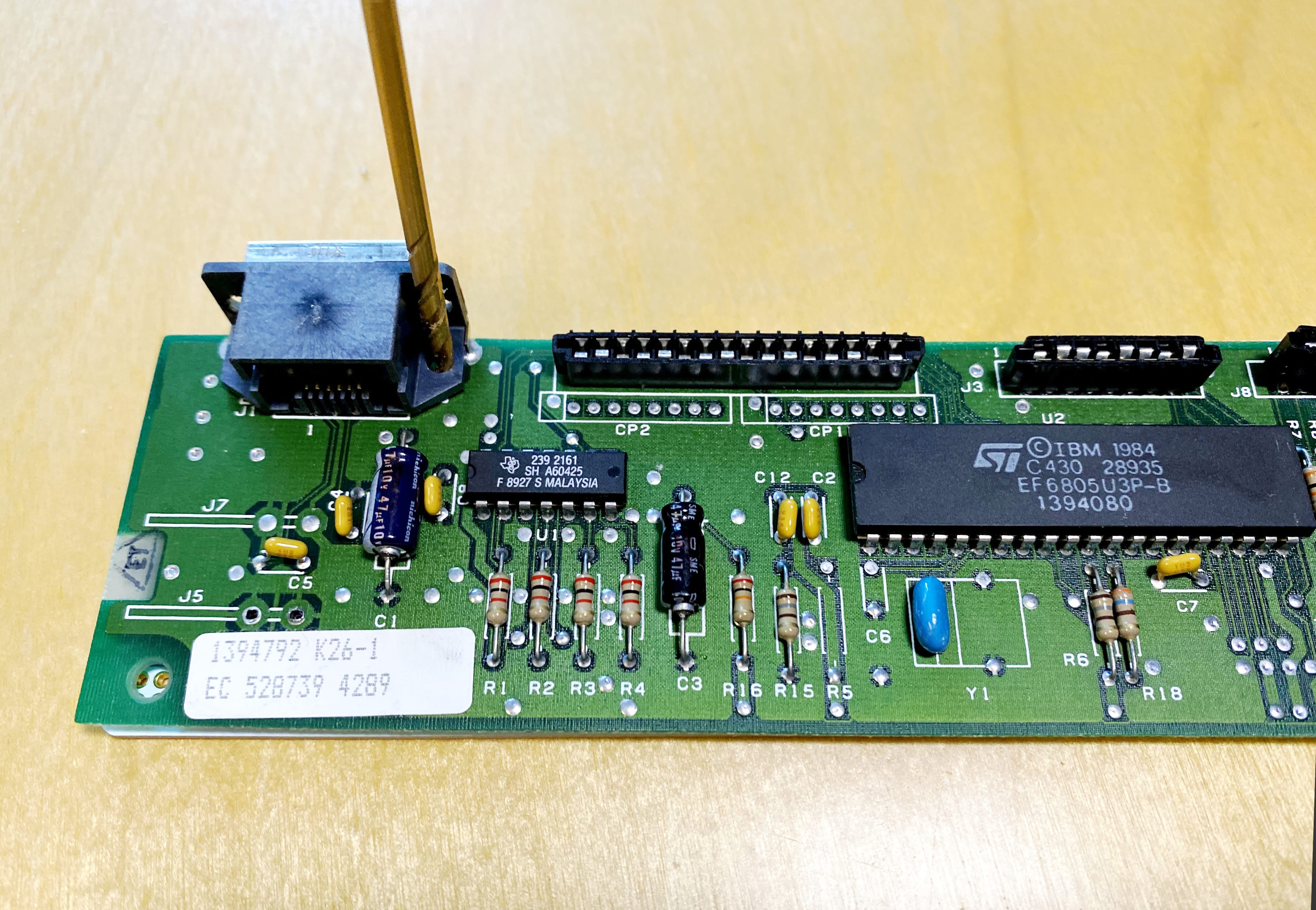
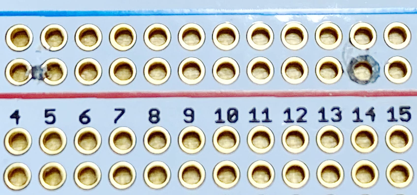
When finished, you should have some visible markings on the Perma-Proto. Using a power drill, finish drilling these two 9/64 inch or 3.5mm holes all the way through the Perma-Proto. You’ll be left with a hole through row 14, and a hole between rows 4 and 5. Drilling these holes allows the Perma-Proto to sit flush against the bottom of the Model M’s case, providing the clearance needed to reinstall the keyboard when we’re all finished.
After drilling, test fit the Perma-Proto to ensure your holes are large enough for the board to sit on the original controller’s registration pins securely. If you find that your drilled holes aren’t quite large enough, use a slightly larger drill bit, or enlarge the hole slightly using the 9/64 inch or 3.5 mm bit. You’re looking for some slight friction, but not an over sized fit.
Assembly of the QMK Controller Board
Thanks to the Model M’s capacitive touch membrane, the assembly for this project is quite simple, really just 5 items. We’ll be utilizing the space on our Perma-Proto to match the positioning of the flat flex cables on the Model M’s keyboard. Because of this, positioning on the Perma-Proto is critical for a proper fit. If you’re starting this build on a breadboard the exact precision is less important, so the following applies to installation on a Perma-Proto.
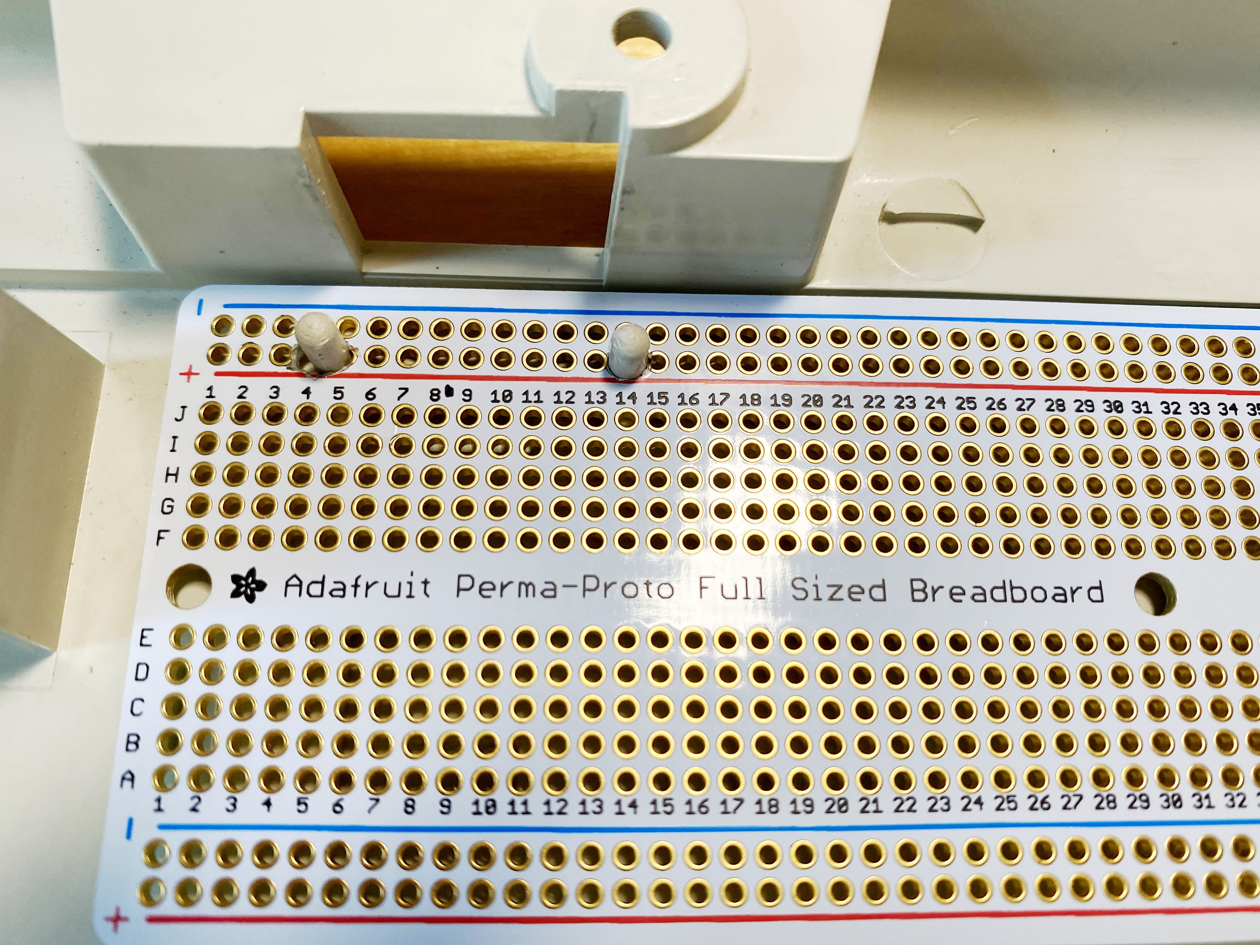
- Install the rear-most set of pins on your Teensy (C7 and F7) in row 21 of the Perma-Proto. Ensure the USB connector on your Teensy is pointing towards row 60 (USB connector is facing away from the holes you previously drilled).
- Install the 16 position flat flex connector directly above the Teensy in column
I, ensuring the first pin of the connector is also installed in row 21 of the Perma-Proto. - Install the 8 or 12 position flat flex connector in the same column (
I) and starting on row 43.- The 8 position connector is for the older Model M
- The 12 position connector is for the newer Model M
- If you have a older Model M, install the 4 position flat flex connector in the same column (
I) and starting on row 55.
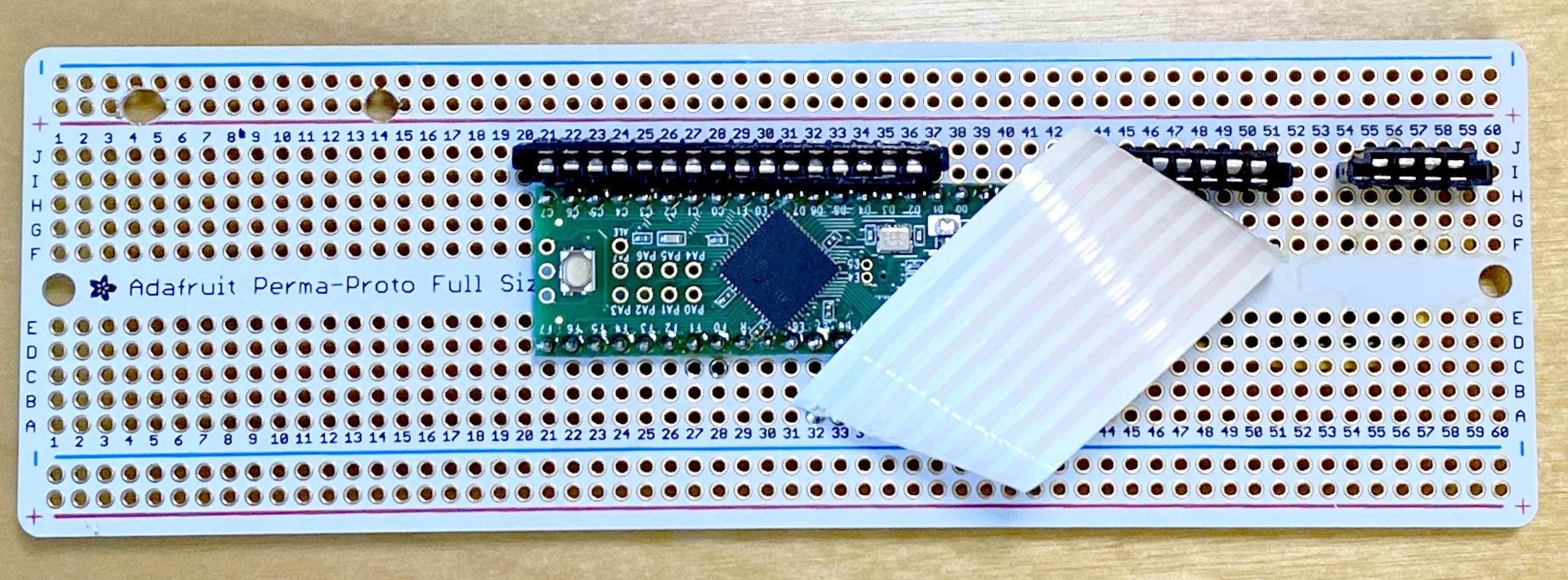
- Solder one side of the 8 pin flat flex cable directly below the 8 position flat flex connector. Ensure that each pin on the cable matches with each pin on the connector. Loop this cable over to the bottom of the Teensy, connecting the cable’s pins to rows 32 - 40 in column
A. This should map to Teensy pins B6, B5, B4, B3, B2, B1, B0, E7.
If you have a newer Model M, you will solder both the 8 pin and the 4 pin flat flex cable next to the 12 pin connector. The 8 pin and the 4 pin connector should be side-by-side and connect to all 12 pins of the 12 pin connector.
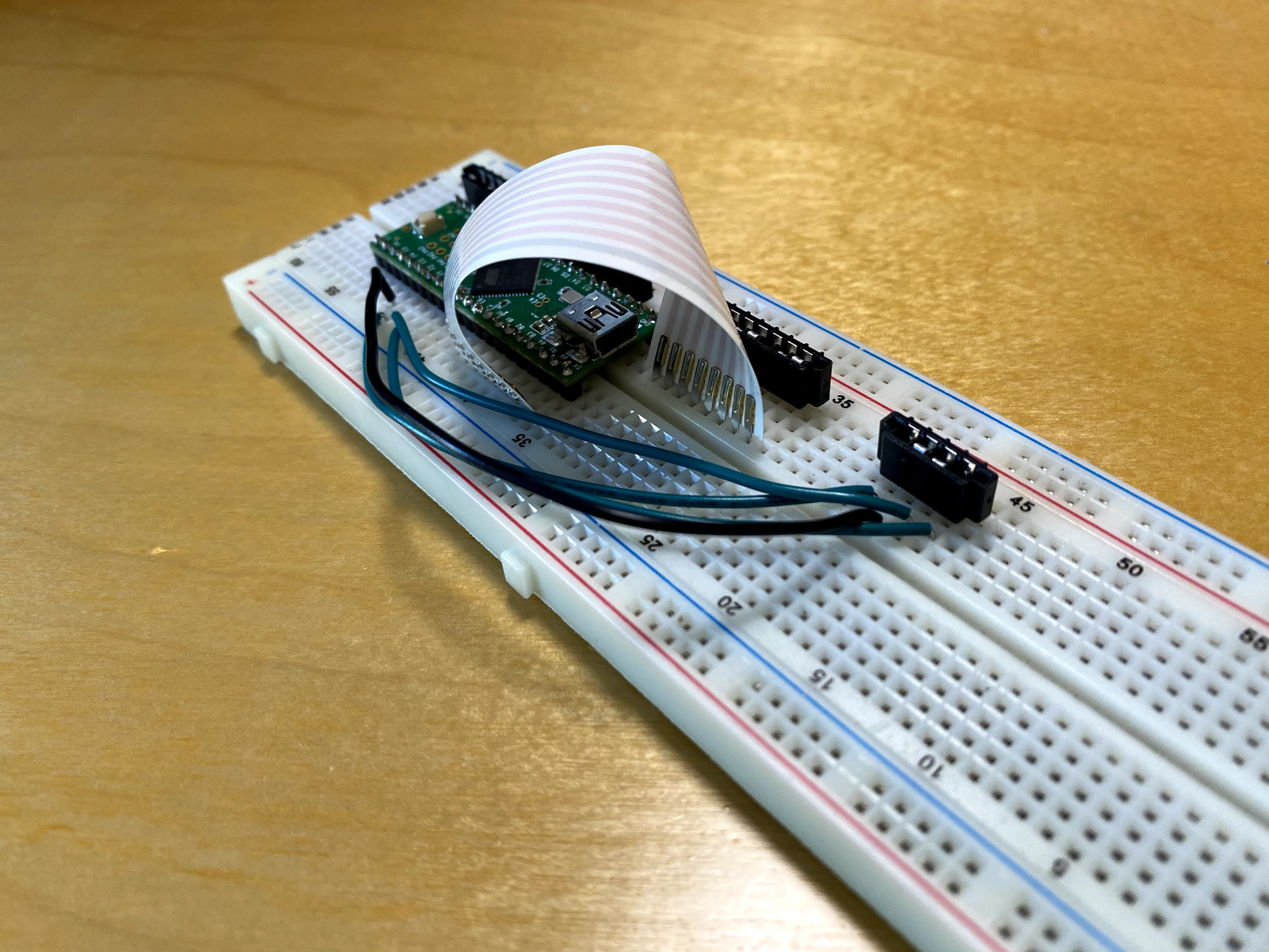
- Loop the 4 pin cable over to the bottom of the Teensy, connecting the cable’s pins to rows 25 - 28 in column
A. This should map to Teensy pins F0, F1, F2, F3. You can see this represented by the blue and black hookup wire in the breadboard prototype photo above. - Once you have everything wired up and soldered in place, you can place the Perma Proto back into the Model M’s case, ensuring it’s firmly seated against the bottom of the case.
- Connect your USB panel cable to the Teensy, loop it around to the original SDL connector opening in the case. You can hot glue, or double-sided tape this panel connector to the inside of the case, which provides a unobtrusive and semi-integrated looking connection for your USB cable.
- The panel mount side of this cable will sit on top of the two registration pins connected to the case, and flush against the back face of the case.
Once you have everything connected and soldered in place, you’re finished with the hardware portion of this project.
QMK Firmware Configuration
For this project I’m using the excellent open source QMK firmware to drive the keyboard and interface with my PC. The documentation is excellent, so I’m just providing a brief tl;dr for how to get QMK configured.
If you wish to get started immediately, at this point you can simply qmk compile --keyboard converter/modelm101 --keymap default which is the baseline configuration this keyboard is built from.
If you wish to customize your Model M’s capabilities further, let’s start by generating a new keymap
qmk new-keymap -kb <keyboard-name>- You should now have a new directory under
$qmk_install_dir/keyboards/ - As an example, I now have
~/src/qmk_firmware/keyboards/IBM_ModelM_2k
cdinto your keyboard directory
I’ll be referring to my IBM Model M QMK configurations throughout the remainder of this tutorial.
config.h
config.h is the file which defines the low-level configuration for our keyboard.
With your favorite editor, open and edit
$qmk_install_dir/keyboards/<keyboard-name>/config.h- Copy the entire contents of my config.h into this file.
- Verify and correct if needed the
MATRIX_ROW_PINSandMATRIX_COL_PINSassignments. If you’ve followed this tutorial exactly, these assignments will not need to be changed.
rules.mk
rules.mkis used to inform QMK what files to build, and what features to enable.With your favorite editor, open and edit
$qmk_install_dir/keyboards/<keyboard-name>/rules.mkCopy the entire contents of my rules.mk into this file
Ensure that you have the following configuration for our Teensy micro controller, and enabling support for media and system keys.
MCU = at90usb1286BOOTLOADER = halfkayEXTRAKEY_ENABLE = yes
<keyboard-name>.h
<keyboard-name>.his what defines your keyboard’s key switch matrix to QMK.To the best of my knowledge all IBM Model M keyboards have the same key switch matrix, so you can simply copy my entire file into your
<keyboard-name>.hfile.<keyboard-name>.c
<keyboard-name>.callows you to inject code, override functionality, and otherwise customize how your keyboard behaves in different situations.For our purposes we’re going to configure the Model M’s Num Lock, Caps Lock and Scroll Lock LEDs within
<keyboard-name.c.Again here, you can simply copy my entire file into your
<keyboard-name>.cfile.keyboard_pre_init_user()andled_update_kb()are the functions used to define and drive the LEDs.keyboard_pre_init_user()defines the pins our LEDs are connected to, and initially disables the LEDs upon keyboard startup (when the keyboard receives power upon computer startup or reconnection of the USB cable).led_update_kb()contains the code which detects a key press for Num Lock, Caps Lock or Scroll Lock, and will the supply power to the Teensy pin for the associated LED, thereby turning on the LED.
keymap.c
keymap.c is used to
define the key mapping
of your keyboard. The configuration within this file is what allows you to truly customize your keyboard.
With your favorite editor, open and edit
$qmk_install_dir/keyboards/<keyboard-name>/keymap.cUnless you really want to hand-type this config, I would recommend copying my entire keymap.c , and editing from there.
- And here’s a simplistic example of a keymap with two layers
I wrote about
keymap.cwith much more detail in my article on how to build a hand-wired keyboard . Head over there if you’re interested in what more you can do.
Building QMK
Once configured to your liking, save this file and try to compile QMK:
cd $qmk_dir
make <keyboard_name>:default
If all goes well, you’ll receive status output like the following:
QMK Firmware 0.9.52
Making IBM_ModelM_2k with keymap default

avr-gcc (GCC) 5.4.0
Copyright (C) 2015 Free Software Foundation, Inc.
This is free software; see the source for copying conditions.  There is NO
warranty; not even for MERCHANTABILITY or FITNESS FOR A PARTICULAR PURPOSE.

Compiling: keyboards/IBM_ModelM_2k/IBM_ModelM_2k.c  [OK]
Compiling: keyboards/IBM_ModelM_2k/keymaps/default/keymap.c  [OK]
Compiling: quantum/quantum.c  [OK]
Compiling: quantum/keymap_common.c  [OK]
Compiling: quantum/keycode_config.c  [OK]
Compiling: quantum/matrix_common.c  [OK]

... snip ...

Linking: .build/IBM_ModelM_2k_default.el  [OK]
Creating load file for flashing: .build/IBM_ModelM_2k_default.hex  [OK]
Copying IBM_ModelM_2k_default.hex to qmk_firmware folder [OK]
CChecking file size of IBM_ModelM_2k_default.hex [OK]
 * The firmware size is fine - 14832/130048 (11%, 115216 bytes free)
If you do receive errors, go back and review your keymap.c file. It’s very easy to forget a comma or forget to include one of your keys.
Once you have a good build for your keyboard, it’s time to flash it to the microcontroller . There’s a lot of variability here, so I would recommend reading through the documentation specific to your setup and microcontroller.
Testing Your Keyboard
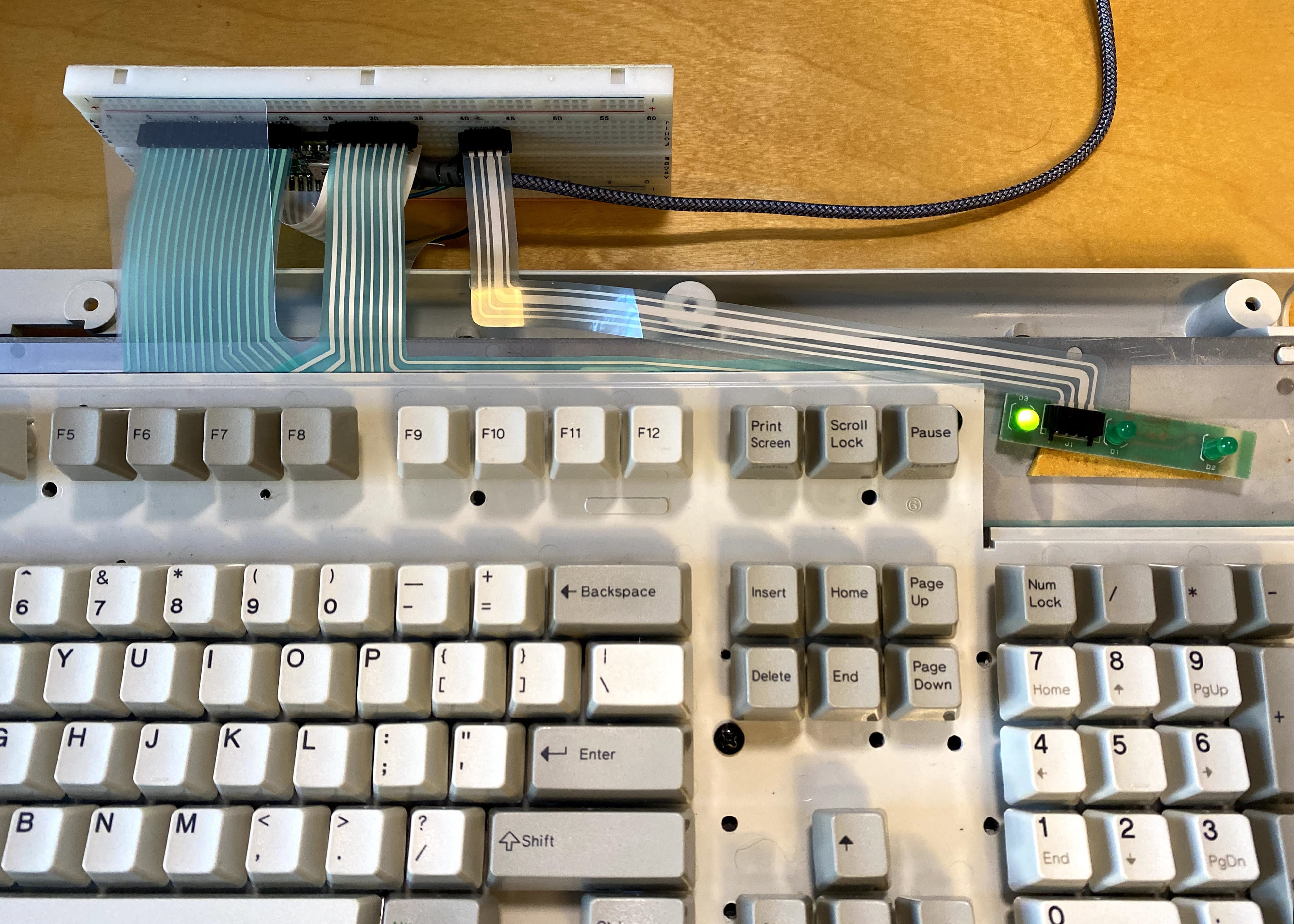
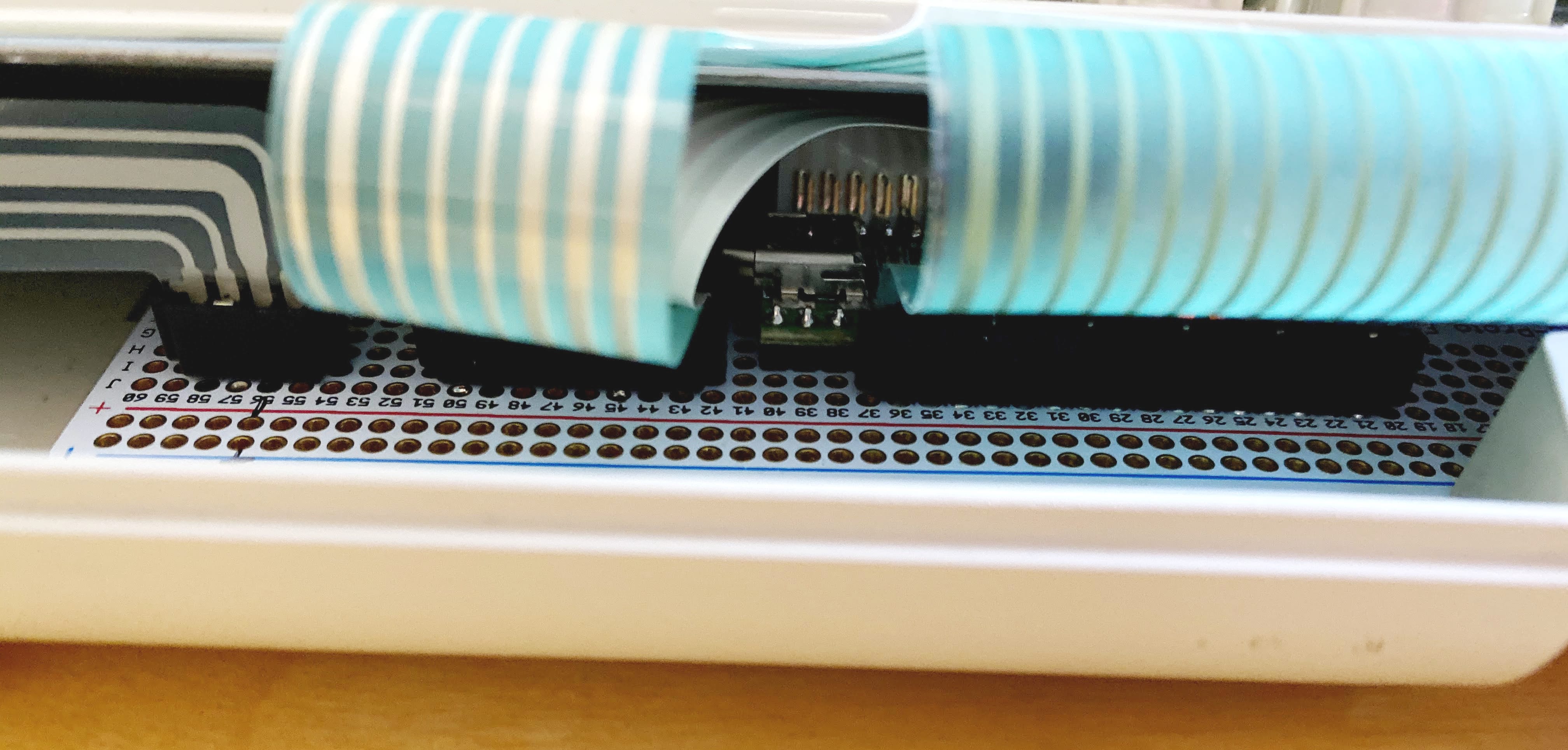
Now that you have the new Teensy and QMK controller board in place, it’s time to connect the Model M’s keyboard membrane. Carefully insert the flat flex cables into the connectors soldered to the Perma Proto. You should find that the connectors on the Perma Proto are perfectly aligned with the flat flex cables on the keyboard. I found the best way to make these connections was to place the keyboard at a 90° angle to the controller board, leaning against a wall, monitor or other vertical surface for balance. Make the connections one at a time, ensuring the flat flex cables are inserted all the way down into their connector.
Once all connections have been made, carefully rotate the keyboard down into the case into it’s normal position.
At this point, you can connect your Model M to your computer via it’s USB cable and begin to test. If all went well, you’ll have a perfectly functioning Model M, upgraded for the modern era!